Wavelength conversion element, light source device, and projector

a technology of light source device and waveguide unit, which is applied in the direction of optical elements, lighting and heating apparatus, instruments, etc., can solve the problems of degrading and affecting the optical use efficiency of the entire system. , to achieve the effect of suppressing the degradation of the optical use efficiency of the entire system

Inactive Publication Date: 2012-05-03
SEIKO EPSON CORP
View PDF26 Cites 118 Cited by
  • Summary
  • Abstract
  • Description
  • Claims
  • Application Information

AI Technical Summary

Benefits of technology

[0056]As a result, the projector can suppress degradation of the optical use efficiency of the entire system.

Problems solved by technology

Therefore, the optical use efficiency over the entire system including the phosphor wheel is degraded.
The light emitted from the phosphor layer with a large angle with respect to the normal line of the emission face of the phosphor layer is difficult to be sufficiently captured by a waveguide unit or a pickup lens provided to the emission side of the phosphor layer.
Therefore, the optical use efficiency is degraded.
In addition, it is possible to also suppress reduction of the use efficiency of the excitation light.

Method used


Image

  • Wavelength conversion element, light source device, and projector
  • Wavelength conversion element, light source device, and projector
  • Wavelength conversion element, light source device, and projector

Examples


first embodiment

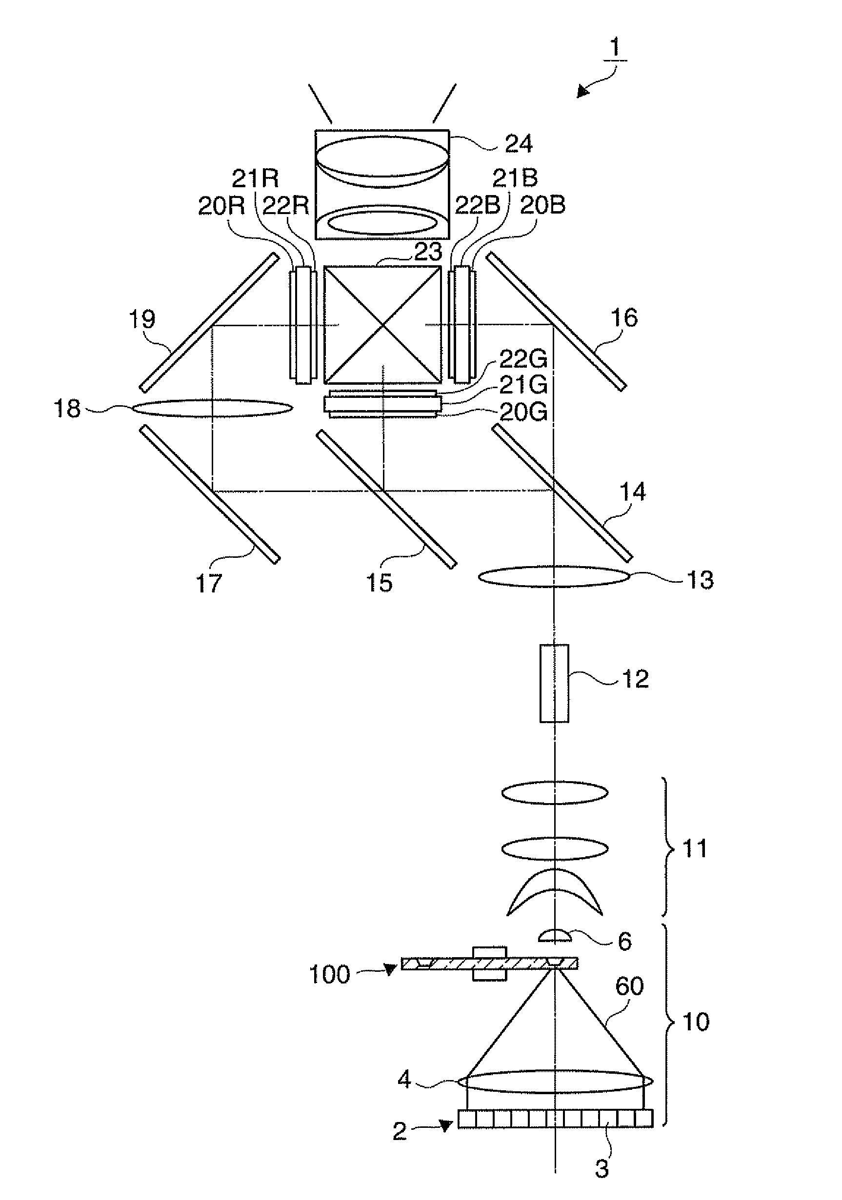
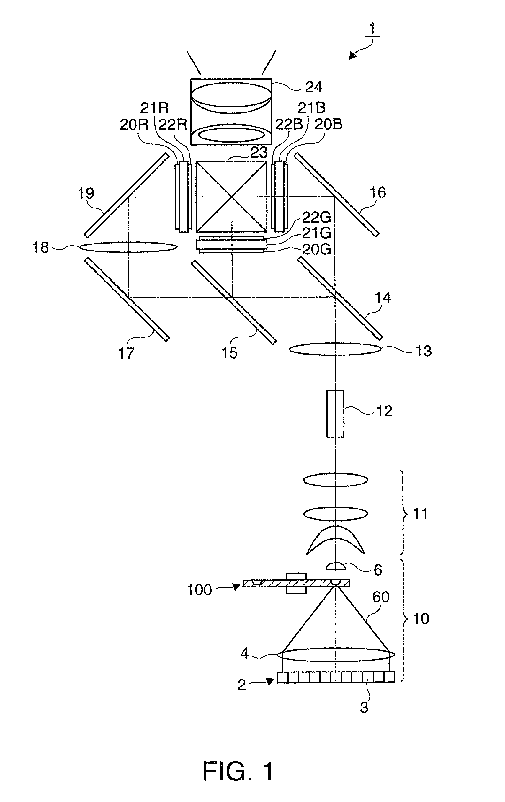
[0088]FIG. 1 is a schematic configuration diagram illustrating a projector 1 according to a first embodiment of the invention. A light source device 10 emits illumination light including red (R), green (G), and blue (B) light beams. The light source device 10 includes a laser diode array 2, a condensing lens 4, a phosphor wheel 100 serving as a wavelength conversion element, and a pickup lens 6.

[0089]The laser diode array 2 includes a plurality of laser diodes 3 arranged in an array shape. The laser diode array 2 serves as an excitation light source unit for emitting an excitation light 60. The excitation light 60 is, for example, blue light (B) having a wavelength of about 450 nm. The condensing lens 4 serves as a light condensing optical system for condensing the excitation light 60 emitted from the laser diode array 2 to the phosphor wheel 100.

[0090]The phosphor wheel 100 emits fluorescent light having a wavelength different from that of the excitation light 60 by being irradiate...

second embodiment

[0125]The projector according to a second embodiment will be described with reference to FIGS. 6 to 10. FIG. 6 is a schematic configuration diagram illustrating a projector 600 according to the second embodiment of the invention. FIG. 7 is a plan view illustrating a phosphor wheel 400. FIG. 8 is a diagram illustrating a cross section C-C″ of the phosphor wheel 400. FIG. 9 is a diagram illustrating a cross section B-B″ of the phosphor wheel 400. FIG. 10 is a plan view illustrating a filter 620.

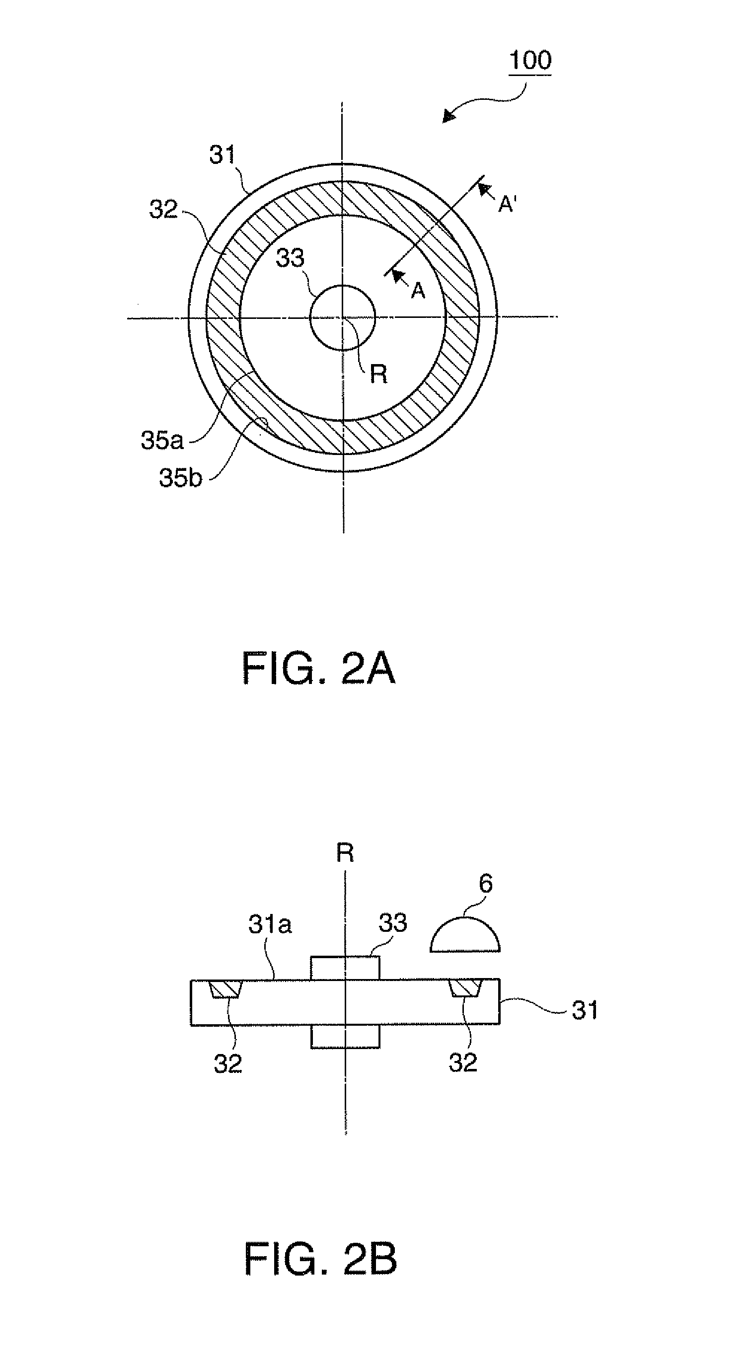
[0126]While a single ring-shaped structural body 32 is provided in the wheel substrate 31 according to the first embodiment, in the phosphor wheel 400 according to the present embodiment, as shown in FIG. 7, a plurality of structural bodies 32R and a plurality of structural bodies 32G are arranged in a ring shape to surround the rotation axis R of the wheel substrate 31. In addition, an opening 433 is provided to penetrate through the cylindrical wheel motor 33. The structural body 32R has a ph...

third embodiment

[0138]FIG. 11 is a cross-sectional view illustrating the main parts of a phosphor wheel 700 serving as a wavelength conversion element according to a third embodiment of the invention. Description will be made for differences from the phosphor wheel 100 of the first embodiment. In the phosphor wheel 700 according to the present embodiment, instead of the dichroic film 38, a reflection layer 72 for reflecting the fluorescent light and the excitation light 60 is provided in a position corresponding to the incident face 36a of the phosphor layer 36 in the structural body 32 of the first embodiment.

[0139]The excitation light 60 is irradiated from the side where the structural body 32 of the wheel substrate 31 is provided to the phosphor 1000 (not shown), and the fluorescent light is generated from the phosphor 1000. Therefore, according to the present embodiment, the emission face 36b of the fluorescent light of the phosphor layer 36 also serves as an incident face on which the excitati...


PUM


Abstract

The phosphor wheel (wavelength conversion element) includes: a substrate; a light-emitting element having at least a phosphor layer provided on one surface of the substrate; and a first reflective portion provided in at least a first side face of the phosphor layer to change a propagation direction of the light propagating inside the phosphor layer such that an angle with respect to a normal line of the emission face where the fluorescent light is emitted from the light-emitting element is reduced.

Description

BACKGROUND[0001]1. Technical Field[0002]The present invention relates to a wavelength conversion element, a light source device, and a projector, and more particularly, to a phosphor wheel for generating fluorescent light that can be preferably used in the wavelength conversion element, the light source device, and the projector.[0003]2. Related Art[0004]As one of light source devices used in the projectors, there has been proposed a light source device that generates a fluorescent light having a wavelength different from that of an excitation light by irradiating laser light as the excitation light to a phosphor (for example, JP-A-2009-277516 and JP-A-2010-86815).[0005]In the related art, the phosphor layer of the phosphor wheel serving as a wavelength conversion element is provided in an area which is larger than the spot of the excitation light formed on the phosphor wheel. A plurality of phosphor particles (phosphor crystals) distributed in the phosphor layer isotropically radia...

Claims


Application Information

Patent Timeline
Patent Type & Authority Applications(United States)
IPC IPC(8): F21V9/16F21V29/00F21V7/00
CPCG02B26/008G03B21/204G03B33/08H04N9/3114G02B1/118
Inventor NOJIMA, SHIGEOKANEKO, TSUYOSHISAWAKI, DAISUKE
Owner SEIKO EPSON CORP
Why Eureka
Try Eureka