System and method for autonomous discovery of peak channel capacity in a wireless communication network

a wireless communication network and wireless communication technology, applied in the field of wireless communication network system and method for autonomous discovery of peak channel capacity, can solve the problems of slow data transfer rate, real possibility of congestion in communication network, and little control of wireless communication device's rate at which data file is transferred

Active Publication Date: 2012-05-03
OPANGA NETWORKS
View PDF7 Cites 29 Cited by
  • Summary
  • Abstract
  • Description
  • Claims
  • Application Information

AI Technical Summary

Benefits of technology

[0120]As discussed above, the wireless communication device 108 uses the data table to determine the expected peak data throughput based on the current measured value of the CINR. For example, using the data from Table 4 (Step 7), the wireless communication device measures the current CINR value if, by way of example, the CINR value is 8 dB, the expected peak throughput rate is 1.0 Mbps. If the actual data throughput rate is lower than this value, the wireless communication device can send a message to the data source 204 via the RAN 110 indicating that it has detected congestion. In response to network congestion, the system 100 can cause the data source 104 to slow down or even temporarily suspend data transfer so as to avoid the undesirable side effects of network congestion. This advantageously allows the system 100 to differentiate between low transfer rates caused by poor quality of the wireless communication link 112 (see FIG. 1) versus low transfer rates caused by network congestion. If the low transfer rate is caused by poor quality of the wireless communication link 112, the wireless communication device 108 can also send a message to the data source 104 via the RAN 110 indicating that the low transfer rate is caused by poor coverage rather than network congestion.
[0123]In yet another embodiment, the data tables for a particular wireless communication device may be prepopulated, thus eliminating the need for a multi-step process illustrated in the data tables above. For example, rather than start with the data tables having a value of zero for all quality levels of the wireless communication link 112, the system 100 may preload the data table and download it to the wireless communication device 108 via the RAN 110. For example, the data of Table 4, Step 7 can be downloaded to the wireless communication device 108 for the particular base station and / or sector with which the wireless communication device is currently communicating. Thus, the wireless communication device begins with a prepopulated data table that reasonably reflects the expected data throughput rates for a given quality value of the wireless communication link 112 (see FIG. 1). The wireless communication device 108 can update the prepopulated data table as discussed above to reflect current system conditions. As noted above, the expected peak data throughput rates may vary based on the type of the wireless communication device 108. Thus, the system 100 must prepopulate the data table with data appropriately selected for the type of wireless communication device 108.
[0125]Thus, the system 100 provides a useful technique for distinguishing between low data transfer rates caused by poor quality of the wireless communication link 112 (see FIG. 1) versus network congestion. The network need only slow down the data transfer rate if network congestion exists. The system allows each wireless communication device to autonomously detect the peak channel capacity and to iteratively populate a data table that may be unique to the wireless communication device, the base station, base station sector, or the like.

Problems solved by technology

Files of this type are often quite large and present the real possibility of causing congestion in the communication network.
When a wireless communication device requests a data file, the wireless communication device has little control over the rate at which the data file is transferred.
A slow data transfer rate may be the result of a poor radio link between the base station and the wireless communication device.
Alternatively, the slow data transfer rate may be result of congestion in the CN or at the RAN.
Congestion at the RAN may occur, for example, if the base station is communicating with a large number of devices and response times are slow.
As noted above, the slowed data transfer rate may be a result of a poor radio link or actual network congestion.
If the slow data transfer rate is the result of a poor radio link, sending a command to the data source to slow down the transfer rate does not relieve congestion in the network and does not improve over all data throughput.

Method used


Image

  • System and method for autonomous discovery of peak channel capacity in a wireless communication network
  • System and method for autonomous discovery of peak channel capacity in a wireless communication network
  • System and method for autonomous discovery of peak channel capacity in a wireless communication network

Examples


Embodiment Construction

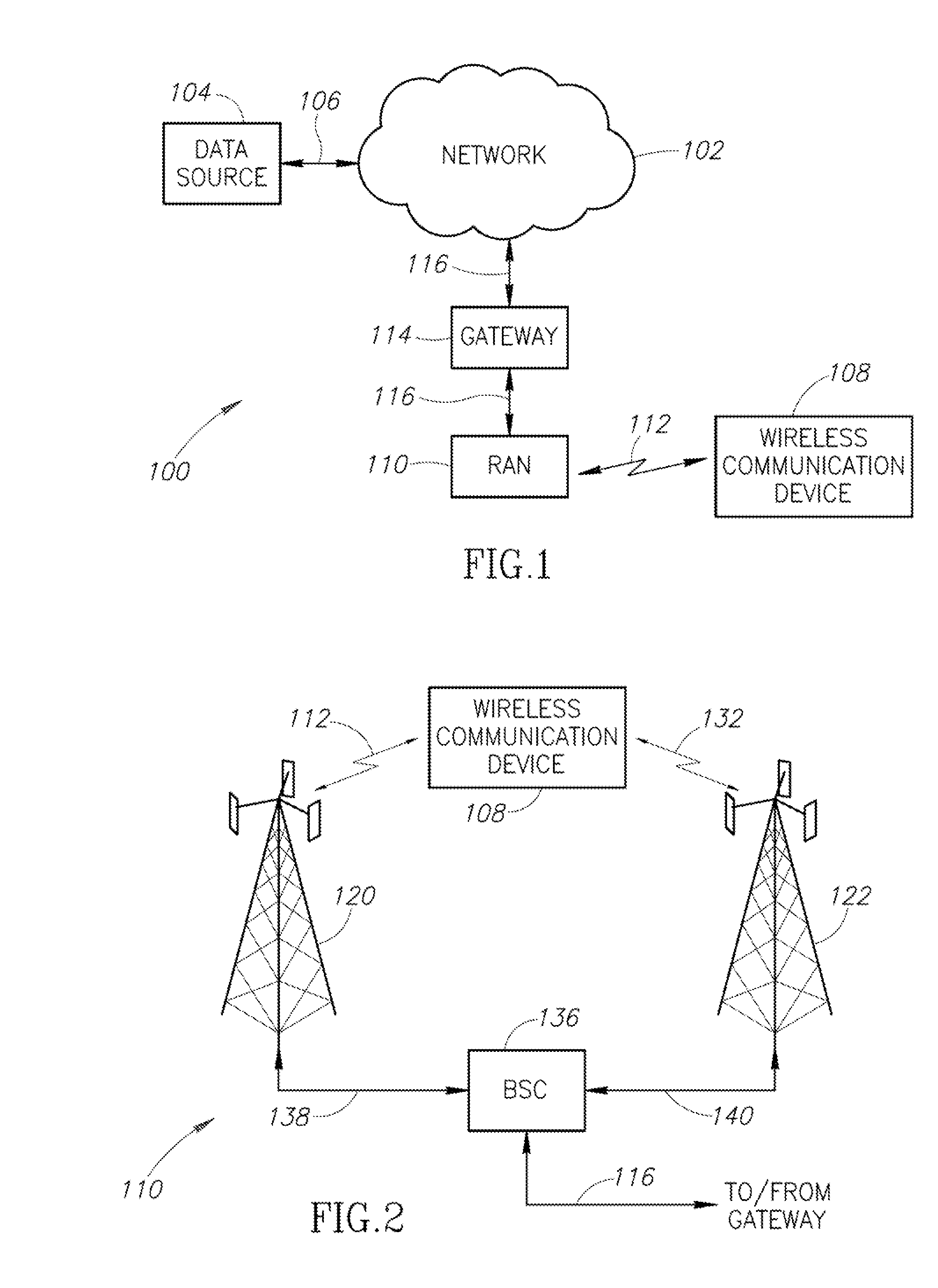
[0019]The present disclosure is directed to a system and method whereby an individual wireless communication device measures a quality value related to the quality of the radio signal connecting the device to a base station. For a particular signal quality level, an associated peak capacity value is determined for that communication link. Similar measurements are performed at other quality signal level values to construct a table or other data storage structure that can equate the quality of the radio link with a maximum data throughput capacity.

[0020]Once such a table is constructed, the wireless communication device, in a subsequent communication, can determine the expected data throughput capacity based on the current quality of the radio link. If the actual transfer rate is below the expected throughput capacity, it may be presumed that the slow data transfer rate is the result of congestion. Alternatively, if the data transfer rate is at or about the expected data transfer rate...


PUM


Abstract

A wireless device includes a data structure that relates peak channel capacity to the quality of the wireless communication link. The wireless communication link quality forms an index to indicate the expected peak channel capacity for that particular quality value of the wireless communication link. The wireless device uses the data storage structure to determine an expected data transfer throughput based on the quality of the wireless communication link. A transfer rate lower than expected may indicate congestion in the core network or the RAN. In this case, the network may slow the data delivery from the data source or temporarily suspend delivery. Conversely, low data throughput may be the result of a poor quality wireless communication link. If the data structure indicates that the data throughput corresponds to the expected throughput for the quality value of the wireless communication link, the system need not take any steps to reduce congestion.

Description

BACKGROUND OF THE INVENTION[0001]1. Field of the Invention[0002]The present disclosure is directed to a system and method for autonomous discovery of peak channel capacity in a wireless communication network and, more specifically, to techniques for a wireless communication device to independently discover the peak channel capacity of a radio link coupling it to a communication network.[0003]2. Description of the Related Art[0004]Wireless communication networks comprise a radio access network (RAN) and a core network (CN). Although different terminology may be used for different systems, the RAN is generally the portion of a telecommunication network that communicates with wireless communication devices, sometimes referred to as user equipment (UE), mobile station (MS), mobile device or the like. For purposes of the present discussion, the terms RAN, UE, MS, and the like may be used interchangeably with other similar terms describing the same functionality.[0005]While the RAN includ...

Claims


Application Information

Patent Timeline
Patent Type & Authority Applications(United States)
IPC IPC(8): H04W24/00
CPCH04L1/0026H04L1/20H04L5/0023H04L5/0033H04W28/02H04W28/0284H04W28/0236
Inventor GORMLEY, EAMMONHARRANG, JEFFREY PAULGIBBONS, DAVID B.
Owner OPANGA NETWORKS
Why Eureka
Try Eureka