
Method and apparatus for indicating destination stations in WLAN system supporting multi-user multiple input multiple output

a wireless local area network and multi-user technology, applied in the field of wireless communication, can solve the problems of ineffective ieee 802.11n medium access control/physical layer (phy) protocol to provide a throughput of above 1 gbps, increase additional overhead, and limit the increase of the throughput of the wireless communication network, so as to achieve the effect of reducing overhead, saving power consumption, and maintaining reliability of data transmission

Active Publication Date: 2012-05-03
LG ELECTRONICS INC
View PDF8 Cites 57 Cited by
  • Summary
  • Abstract
  • Description
  • Claims
  • Application Information

AI Technical Summary

Benefits of technology

[0021]According to the present invention, overhead can be reduced when a group identifier (ID) of a plurality of destination stations is introduced to indicate the destination stations in a wireless local area network (WLAN) system supporting multi-user multiple input multiple output (MU-MIMO).
[0022]By using transmit power adaptively determined based on a channel condition or the like of each destination station in the WLAN system supporting MU-MIMO, power consumption can be saved while maintaining reliability of data transmission.

Problems solved by technology

However, an IEEE 802.11n medium access control (MAC) / physical layer (PHY) protocol is not effective to provide a throughput of above 1 Gbps.
This is because the IEEE 802.11n MAC / PHY protocol is designed for an operation of a station (STA), that is, an STA having one network interface card (NIC), and thus when a frame throughput is increased while conforming to the conventional IEEE 802.11n MAC / PHY protocol, a resultant additional overhead is also increased.
Consequently, there is a limitation in increasing a throughput of a wireless communication network while conforming to the conventional IEEE 802.11n MAC / PHY protocol, that is, a single STA architecture.

Method used


Image

  • Method and apparatus for indicating destination stations in WLAN system supporting multi-user multiple input multiple output
  • Method and apparatus for indicating destination stations in WLAN system supporting multi-user multiple input multiple output
  • Method and apparatus for indicating destination stations in WLAN system supporting multi-user multiple input multiple output

Examples


Embodiment Construction

[0029]Hereinafter, exemplary embodiments of the present invention will be described with reference to the accompanying drawings.

[0030]A wireless local area network (WLAN) system according to an embodiment of the present invention includes at least one basic service set (BSS). The BSS is a set of stations (STAs) successfully synchronized to communicate with one another. The BSS can be classified into an independent BSS (IBSS) and an infrastructure BSS.

[0031]The BSS includes at least one STA and an access point (AP). The AP is a functional medium for providing a connection to STAs in the BSS through respective wireless media. The AP can also be referred to as other terminologies such as a centralized controller, a base station (BS), a scheduler, etc.

[0032]The STA is any functional medium including a medium access control (MAC) and wireless-medium physical layer (PHY) interface satisfying the institute of electrical and electronics engineers (IEEE) 802.11 standard. The STA may be an AP...


PUM


Abstract

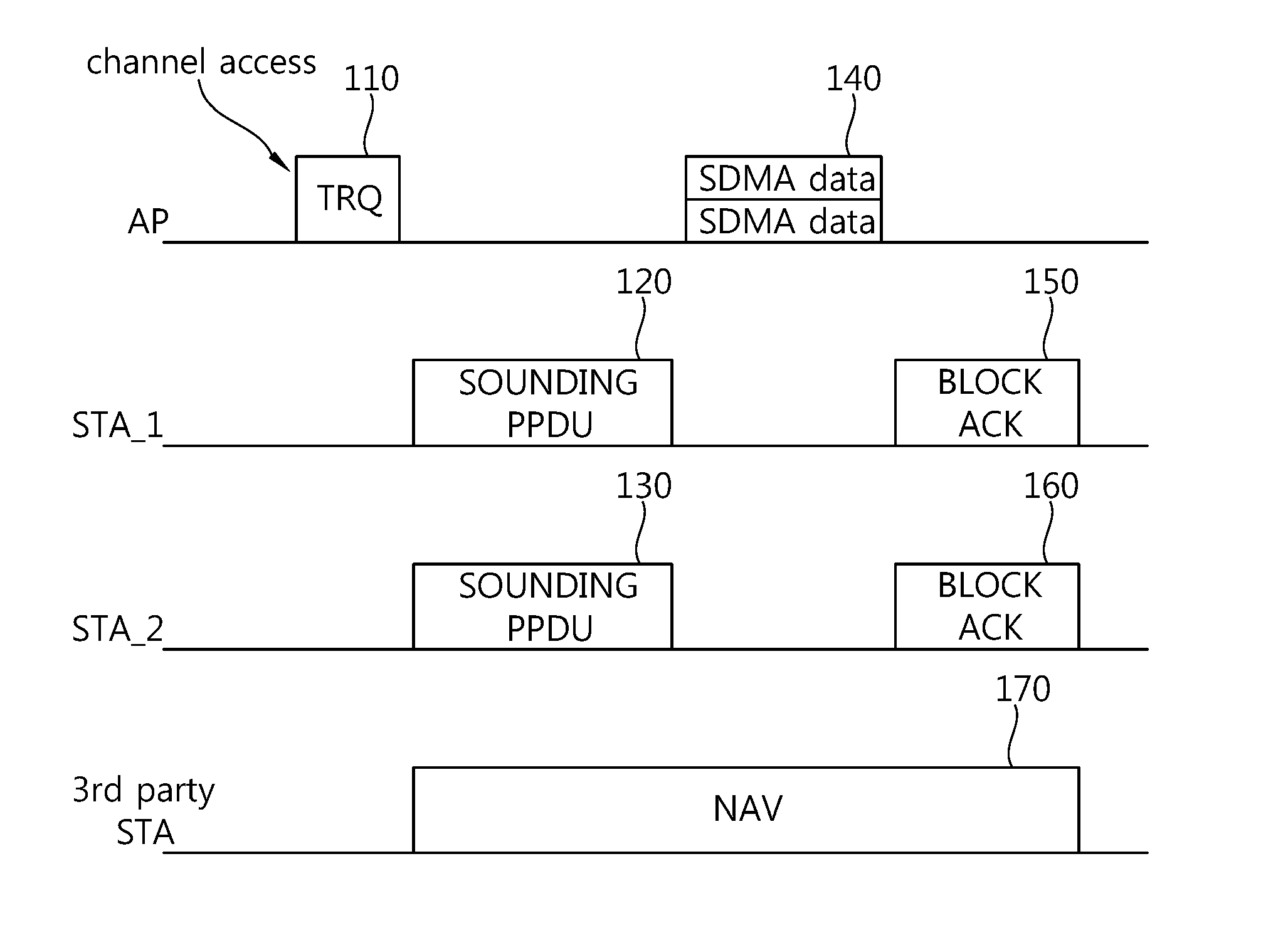
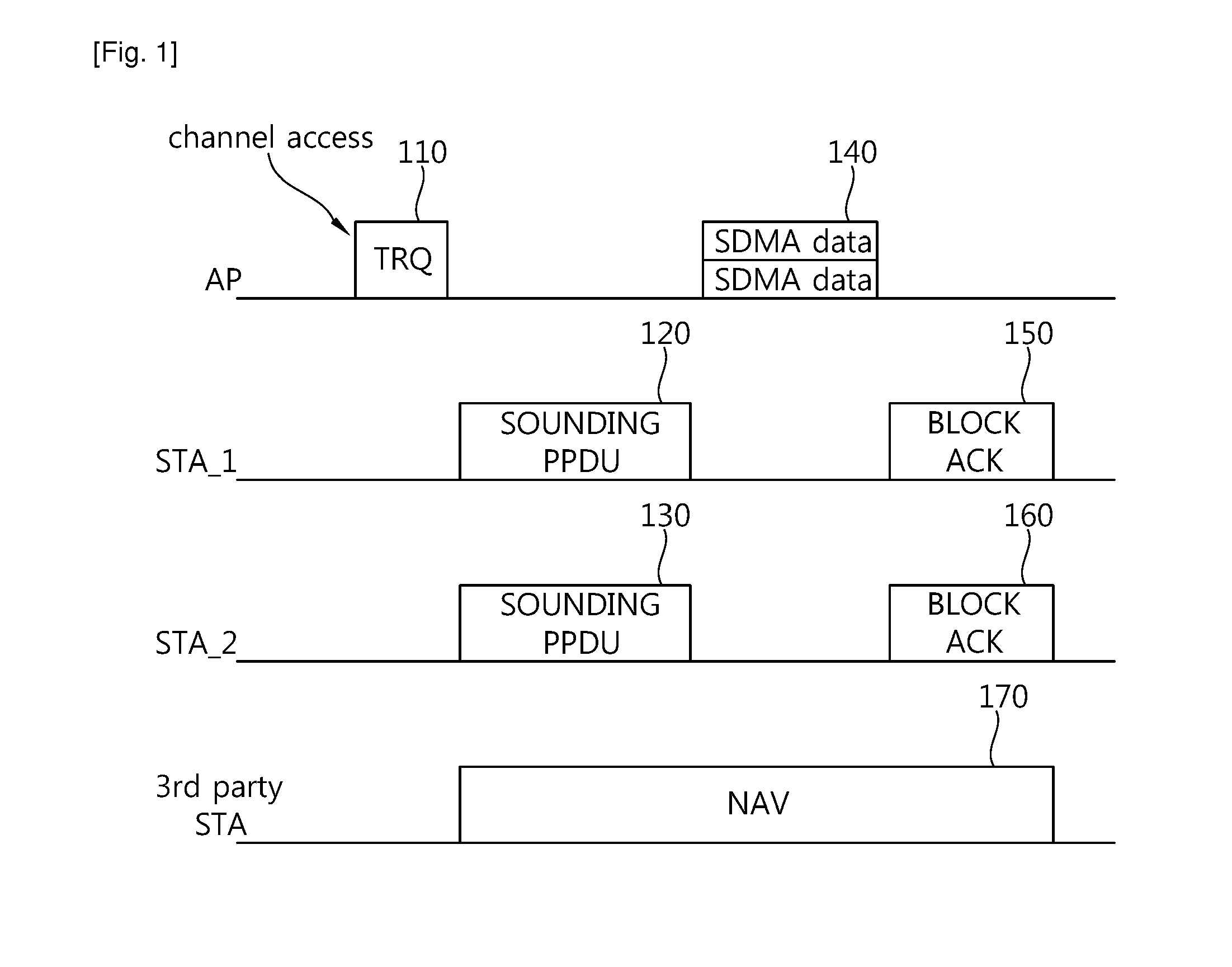
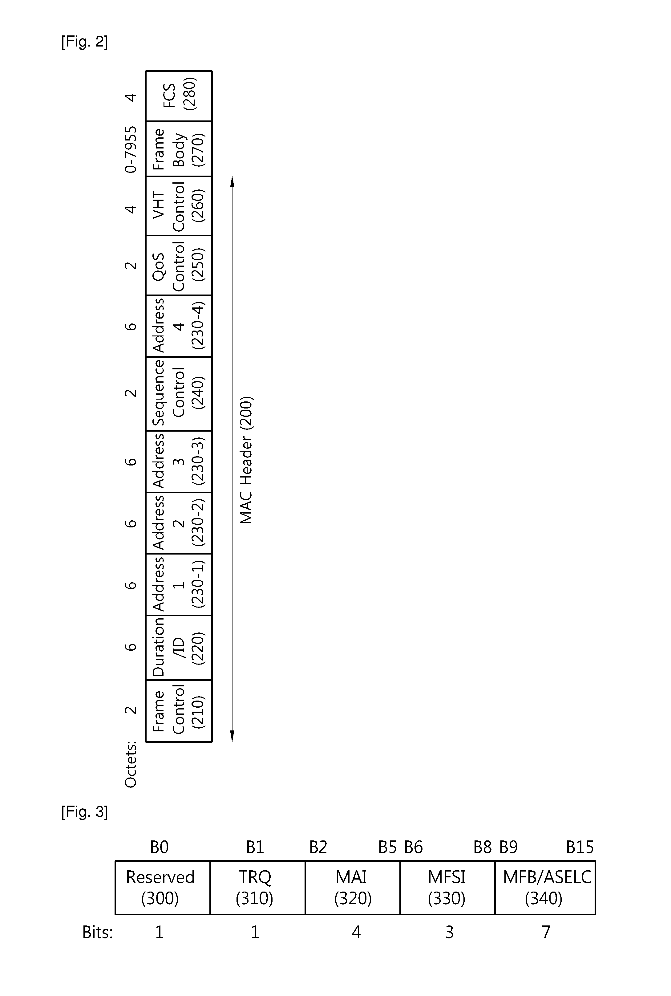
A method of indicating destination stations, performed by an access point (AP), in a wireless local area network (WLAN) system supporting multi-user multiple input multiple output (MU-MIMO) is provided. The method includes transmitting a sounding request frame to the plurality of destination stations to transmit a sounding frame used for channel estimation between the AP and each destination station, receiving the sounding frame in response to the sounding frame request from each station, and transmitting a first data frame spatially multiplexed with respect to the plurality of destination stations by performing channel estimation on the basis of the sounding frame, wherein the sounding request frame comprises a group identifier (ID) indicating the plurality of destination stations.

Description

TECHNICAL FIELD[0001]The present invention relates to wireless communications, and more particularly, to a method and apparatus for indicating destination stations in a wireless local area network (WLAN) system supporting multi-user multiple input multiple output (MU-MIMO).BACKGROUND ART[0002]With the advancement of information communication technologies, various wireless communication technologies have recently been developed. Among the wireless communication technologies, a wireless local area network (WLAN) is a technology whereby Internet access is possible in a wireless fashion in homes or businesses or in a region providing a specific service by using a portable terminal such as a personal digital assistant (PDA), a laptop computer, a portable multimedia player (PMP), etc.[0003]Ever since the institute of electrical and electronics engineers (IEEE) 802, i.e., a standardization organization for WLAN technologies, was established in February 1980, many standardization works have...

Claims


Application Information

Patent Timeline
IPC IPC(8): H04W84/02
CPCH04B7/0452H04L5/0023H04L5/0048H04L25/0204H04L25/0226H04W4/06H04W8/26H04W24/00H04W48/08H04W52/346H04W84/12H04W88/08
Inventor SEOK, YONG HOKANG, BYEONG WOONOH, YU JINLEE, DAE WON
Owner LG ELECTRONICS INC
Learn More