Reducing contamination by regulating flow

a technology of regulating flow and reducing contamination, applied in optics, instruments, electrography/magnetography, etc., can solve the problems of reducing image quality and printer reliability, increasing the risk of damage to the roller in contact with the seal, and mechanical wear between the seal and the member it is in contact, so as to reduce backflow, reduce the flow of contaminating substances, and reduce the effect of surface wear

a technology of regulating flow and reducing contamination, applied in optics, instruments, electrography/magnetography, etc., can solve the problems of reducing image quality and printer reliability, increasing the risk of damage to the roller in contact with the seal, and mechanical wear between the seal and the member it is in contact, so as to reduce backflow, reduce the flow of contaminating substances, and reduce the effect of surface wear

US20120107011A1Inactive Publication Date: 2012-05-03EASTMAN KODAK CO

Image

  • Reducing contamination by regulating flow
  • Reducing contamination by regulating flow
  • Reducing contamination by regulating flow

Examples


Embodiment Construction

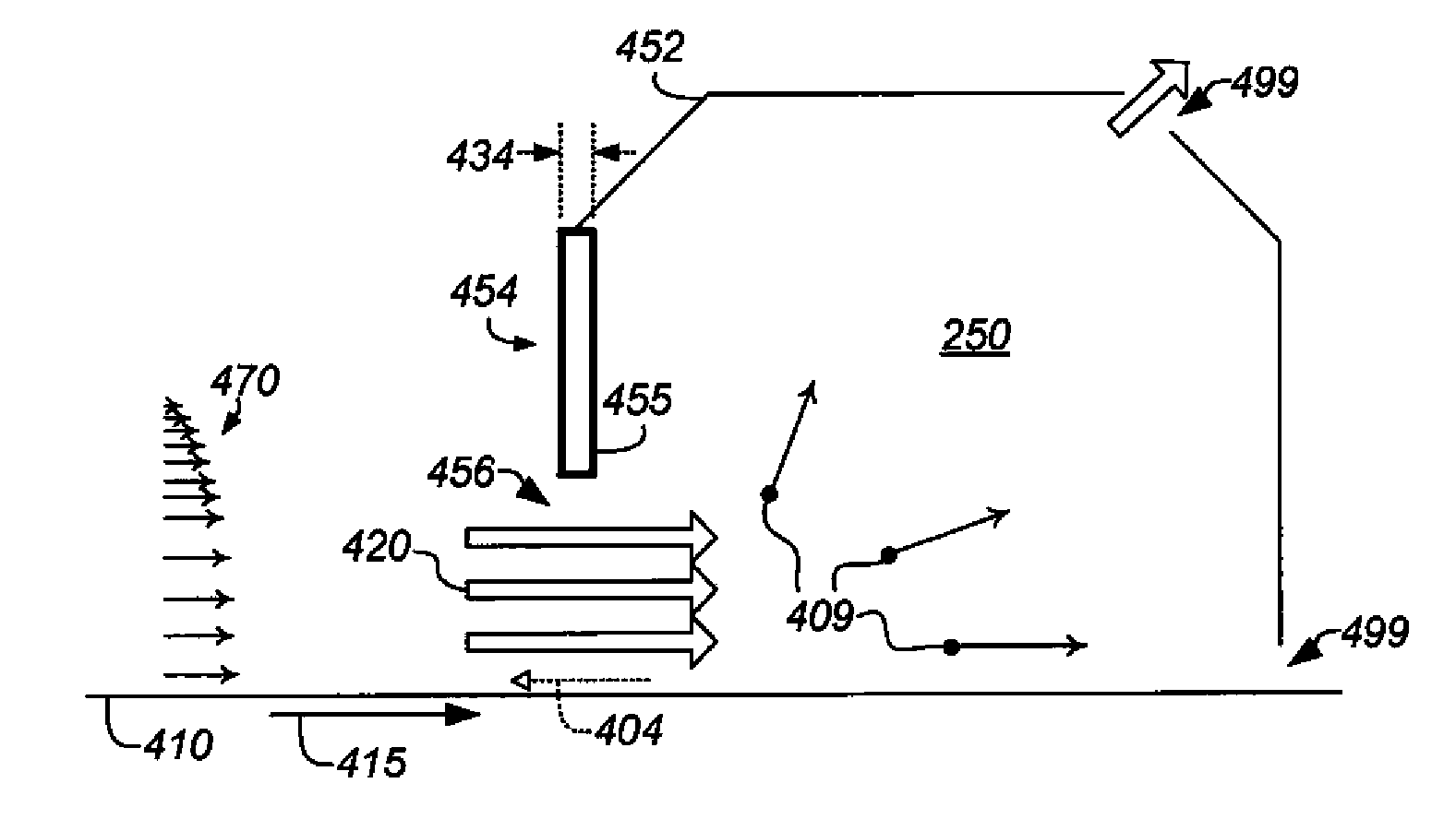
[0029]FIG. 4 shows an apparatus for retaining a contaminating substance 409 in working volume 250 according to an embodiment. A “contaminating substance,” or “contaminant,” as used herein, is any matter (solid, liquid, gas, plasma, or combination, e.g., suspension) that can contaminate a particular surface or part on contact therewith. Not all contaminating substances or contaminants deposit on or contaminate all surfaces or parts, but such substances have the potential to do so. It is therefore desirable to restrict the passage of contaminating substances out of working volumes in which they are found, and in which they are preferably contained. An example of undesirable contamination is the deposition of toner particles on a photodiode in a densitometer in a printer, as described in U.S. Pat. No. 5,903,800 to Stern et al., issued May 11, 1999, the disclosure of which is incorporated herein by reference.

[0030]Movable surface 410 moves in direction 415 and is disposed adjacent to wo...


PUM


Abstract

Apparatus for retaining a contaminating substance in a working volume containing a gas includes a movable surface disposed adjacent to the working volume. A barrier is spaced apart from the surface ahead of the working volume in the direction of motion of the surface so that a gap is defined between the barrier and the surface. The gap is selected so that a stream of gas is carried by the moving surface through the gap into the working volume and the contaminating substance in the working volume is urged away from the gap, thereby reducing flow of the contaminating substance through the gap.

Description

FIELD OF THE INVENTION[0001]This invention pertains to the field of fluid mechanics and more particularly to managing flow through apertures.BACKGROUND OF THE INVENTION[0002]Electrophotography is a useful process for printing images on a receiver (or “imaging substrate”), such as a piece or sheet of paper or another planar medium, glass, fabric, metal, or other objects as will be described below. In this process, an electrostatic latent image is formed on a photoreceptor by uniformly charging the photoreceptor and then discharging selected areas of the uniform charge to yield an electrostatic charge pattern corresponding to the desired image (a “latent image”).[0003]After the latent image is formed, charged toner particles are brought into the vicinity of the photoreceptor and are attracted to the latent image to develop the latent image into a visible image. Note that the visible image may not be visible to the naked eye depending on the composition of the toner particles (e.g., cl...

Claims


Application Information

Patent Timeline
03 May 2012
Publication
US20120107011A1
IPC
G03G21/00
CPC
G03G21/0005; G03G21/206
Inventors
BROWN, KENNETH J.; DOBBERTIN, MICHAEL T.