Burner control systems and methods of operating a burner

a control system and burner technology, applied in the direction of fuel supply regulation, combustion process, lighting and heating apparatus, etc., can solve problems such as maintaining incorrect settings, and achieve the effect of improving the safety of the control system

Inactive Publication Date: 2012-05-03
AUTOFLAME ENG
View PDF6 Cites 18 Cited by
  • Summary
  • Abstract
  • Description
  • Claims
  • Application Information

AI Technical Summary

Benefits of technology

[0012]The flows of air and fuel may be controlled by air and fuel valves respectively. The burner control system may further include a store for storing pairs of values of air and fuel valve settings for varying firing rates of the burner. Such a system provides a simple way of accurately controlling air and fuel flows at different firing rates of the burner. For firing rates between the stored settings, values of air and fuel valve settings can be interpolated.
[0013]In an especially preferred control system, for each pair of values of air and fuel valve settings, a respective value of air pressure of the airflow to the burner is arranged to be stored. The control system may further include an air pressure sensor for sensing the respective value of air pressure of the airflow. The control system may then be arranged to monitor the air pressure at a given firing rate and compare the monitored air pressure with the stored air pressure value corresponding to that firing rate, or to an interpolated value if the firing rate is between those to which stored air and fuel valve settings relate. Similarly, for each pair of values of air and fuel valve settings a respective value of fuel pressure of the fuel flow to the burner may be arranged to be stored. This may be as an alternative to storing a respective value of air pressure but is preferably in addition to that. The control system may further include a fuel pressure sensor for sensing the respective value of pressure of the fuel flow. The control system may then be arranged to monitor the fuel pressure at a given firing rate and compare the monitored fuel pressure with the stored fuel pressure value corresponding to that firing rate, or to an interpolated value if the firing rate is between those to which stored air and fuel valve settings relate. With either of the arrangements described in this paragraph, it becomes possible to provide a control system which is able to react almost instantly to a sudden change in air or fuel pressure, rather than waiting for a feedback system such as an exhaust gas analyser to detect such a problem. That can improve the safety of the control system considerably. For example, the control system may be designed to shut down the burner in the event that the air or fuel pressure departs by more than, say, 10 percent from the stored value, or an interpolated value of the stored value.

Problems solved by technology

Even so, there is inevitably a significant period of time before the feedback from the exhaust gas analyser can be used to correct the setting of the air valve and, until the correction is made, the incorrect setting is maintained.
That is disadvantageous both in respect of relatively small deviations that may be due to relatively common minor variations in conditions or in respect of less common and much bigger deviations, for example, arising from a major drop in airflow caused by a plastic bag being sucked into the air inlet of the burner and obstructing it.

Method used


Image

  • Burner control systems and methods of operating a burner
  • Burner control systems and methods of operating a burner

Examples


Embodiment Construction

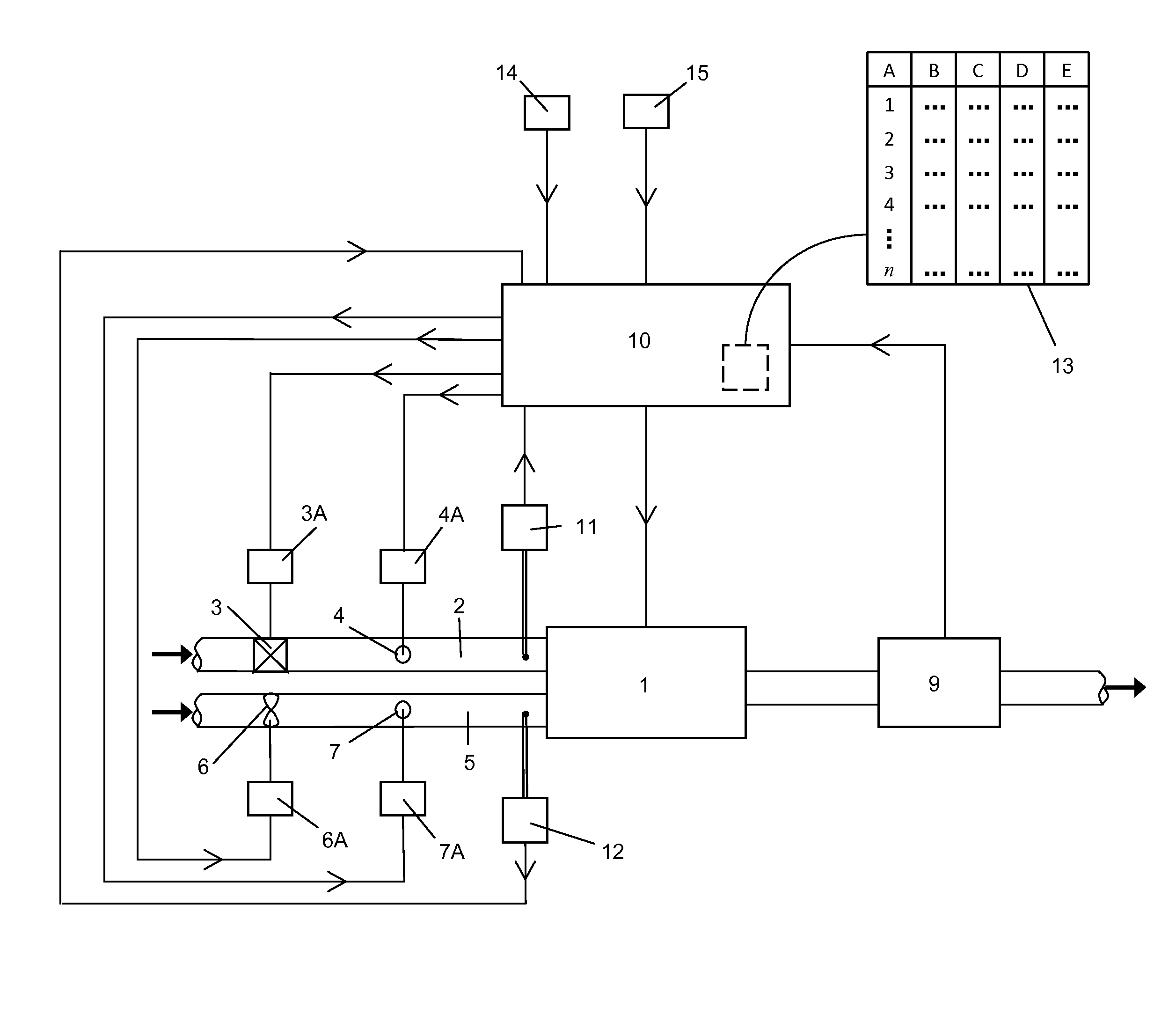
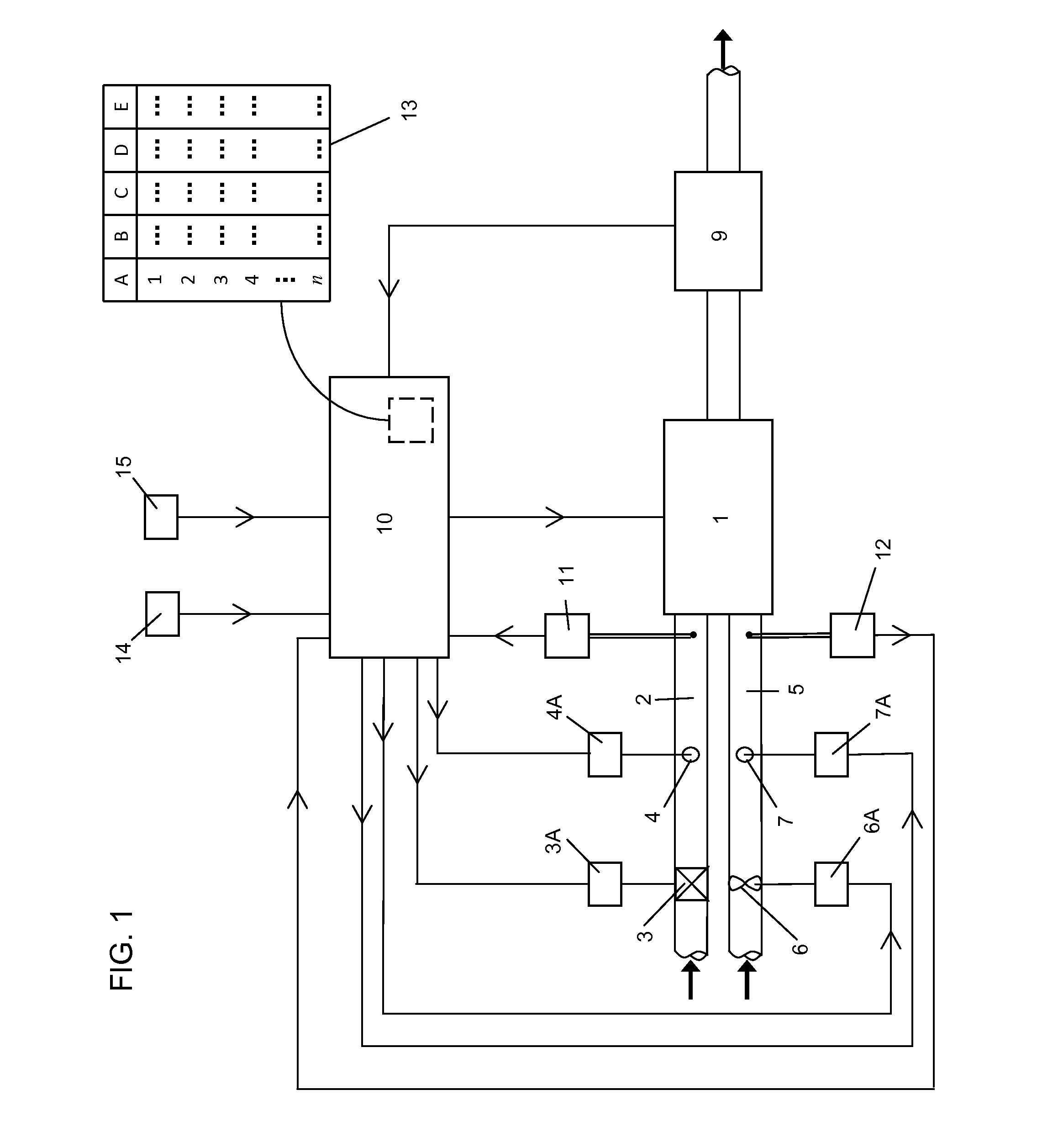
[0027]Referring to FIG. 1, a burner control system comprises a fuel burner 1 which in this case is a gas burner and to which gas is fed along a duct 2 via a fan 3 and a butterfly valve 4 and to which air is fed along a duct 5 via a fan 6 and a butterfly valve 7. In the burner 1, the gas and air are mixed and combustion takes place. The products of combustion pass from the burner 1 along a duct 8 where an exhaust gas analysis system 9 is placed for analysing the products of combustion. A control unit 10 is provided to control the operation of the burner 1, by controlling the valves 4 and 7 via servomotors 4A and 7A to adjust the gas and air flow rates. The operation of the fans 3 and 6 by motors 3A and 6A is also controlled by the control unit 10.

[0028]The arrangement described above may be essentially as shown and described in GB 2138610A with the exhaust gas analysis system 9 being essentially as shown and described in GB 2169726A. As already indicated, the disclosures of both GB 2...


PUM


Abstract

Burner control systems and methods of operating a burner are for a large boiler such as might be used in hospitals, hotels, offices or other large commercial or domestic premises.

Description

[0001]This application claims priority to United Kingdom application serial no. 1018178.2 filed on Oct. 28, 2010, and which application is incorporated herein by reference. To the extent appropriate, a claim of priority is made to the above disclosed application.TECHNICAL FIELD[0002]This invention relates generally to burner control systems and to methods of operating a burner. The invention relates in particular, but not exclusively, to a burner for a large boiler such as might be used in hospitals, hotels, offices or other large commercial or domestic premises.BACKGROUND OF THE INVENTION[0003]A known burner control system is described in GB 2169726A which also refers to GB 2138610A. The disclosure of both those specifications is incorporated herein by reference. In that control system the flows of air and fuel are controlled by air and fuel valves respectively, and pairs of values of air and fuel valve settings are stored for varying firing rates of the burner. Those air and fuel ...

Claims


Application Information

Patent Timeline
Patent Type & Authority Applications(United States)
IPC IPC(8): F23N3/04F23N5/00
CPCF23N1/022F23N5/003F23N5/184F23N5/242F23N2005/181F23N2005/185F23N2023/54F23N2025/06F23N2025/14F23N2031/00F23N2031/18F23N2031/26F23N2035/06F23N2035/12F23N5/18F23N2223/54F23N2225/14F23N2225/06F23N2231/00F23N2231/18F23N2231/26F23N2235/12F23N2235/06F23N1/00F23N3/00F23N5/26
Inventor KEMP, BRENDAN
Owner AUTOFLAME ENG
Why Eureka
Try Eureka