Method of fabricating flexible artificial retina devices

a flexible, integrated circuit technology, applied in the direction of head electrodes, solid-state devices, semiconductor devices, etc., can solve the problems of increasing the number of electrical interconnections between the micro electrode chips and the driving circuit chips, severely limited field of view provided by such devices, and achieve the effect of high electrical excitation resolution

Active Publication Date: 2012-05-03
IRIDIUM MEDICAL TECH
View PDF4 Cites 26 Cited by
  • Summary
  • Abstract
  • Description
  • Claims
  • Application Information

AI Technical Summary

Benefits of technology

[0007]In one embodiment, a flexible integrated device can provide high resolution of electrical excitations (e.g. down to individual retina cell level) over at least one mm (millimeter) to several mm of retina area corresponding to a few degrees to a few tens of degrees field of view for retina prosthesis. The flexible integrated device may be capable of tuning and calibration for adjusting excitation to target retinal neurons. In one embodiment, the flexible integrated device may be implanted using either an epi-retinal (e.g. from the front side of retina facing the incoming light or on the retina) approach or a sub-retinal (e.g. behind the retina) approach.
[0010]In another embodiment, a flexible integrated device may include electrodes fitted with local return paths (or “guard ring”) to confine and shorten the total distance of electric flows from the electrodes. As a result, the amount of electricity lost in transit of the electric flows can be lowered to prevent unwanted stimulation of neural cells farther away from the target neuron cells, such as the bipolar cells or ganglion cells in the sub-retina case. The surfaces of electrodes may be positioned in three dimensions manner with multiple electrode heights from the substrate of the device to differentially stimulate different layers of neuron cells, such as strata of ON and OFF cells.
[0012]In another embodiment, a provision system including a flexible integrated retina chip implanted to a user as retina prosthesis may allow fine tuning of the chip via external commands. For example, each pixel unit in the chip may include specific receivers and / or circuitry for receiving optical and / or wireless communication signals for the external commands to select and / or configure portions of the chip according to the user's visual perception. The provision system may include a remote control to issue the external commands optically or wirelessly.
[0015]In another embodiment, a fabrication method for a device implantable for a retina may comprise forming an array of pixel units over a substrate. Each pixel unit can include a photo sensor, a micro electrode and processing circuitry coupled to the photo sensor and the electrode. Each pixel unit may be coupled with neighboring pixel units in the array with conducting wires. The substrate may be thinned to a thickness to allow bending of the device to position the pixel units over a curved area conforming to the curvature of a retina. The device may be covered with protected layers that are biocompatible to provide bi-directional protection between the device and tissues associated with the retina. A plurality of perforation holes may be opened up between the pixel units perpendicular to the chip surface to allow fluidic flow through the devices via the perforation holes. The micro electrodes of the pixel units may be exposed through the protected layers.

Problems solved by technology

However, field of view provided by such devices, which depends on the number of micro electrodes and pitch of micro electrodes included in the device, may be severely limited because of size limitation on the wiring implant.
Thus, the required number of electrical interconnections between the micro electrode chips and the driving circuit chips can increase significantly and impose unnecessary ceilings on achievable number of pixels.
As a result, additional interferences among the micro electrodes may occur because of the mismatch in shapes to further limit possible image resolution of the device.
Thus, traditional retina prosthesis devices are inherently limited to provide levels of image resolutions, field of views or other visual characteristics to achieve levels close to a real retina to help patients recover from impaired vision capabilities.

Method used


Image

  • Method of fabricating flexible artificial retina devices
  • Method of fabricating flexible artificial retina devices
  • Method of fabricating flexible artificial retina devices

Examples


Embodiment Construction

[0032]Methods of fabricating flexible artificial retina devices are described herein In the following description, numerous specific details are set forth to provide thorough explanation of embodiments of the present invention. It will be apparent, however, to one skilled in the art, that embodiments of the present invention may be practiced without these specific details. In other instances, well-known components, structures, and techniques have not been shown in detail in order not to obscure the understanding of this description.

[0033]Reference in the specification to “one embodiment” or “an embodiment” means that a particular feature, structure, or characteristic described in connection with the embodiment can be included in at least one embodiment of the invention. The appearances of the phrase “in one embodiment” in various places in the specification do not necessarily all refer to the same embodiment.

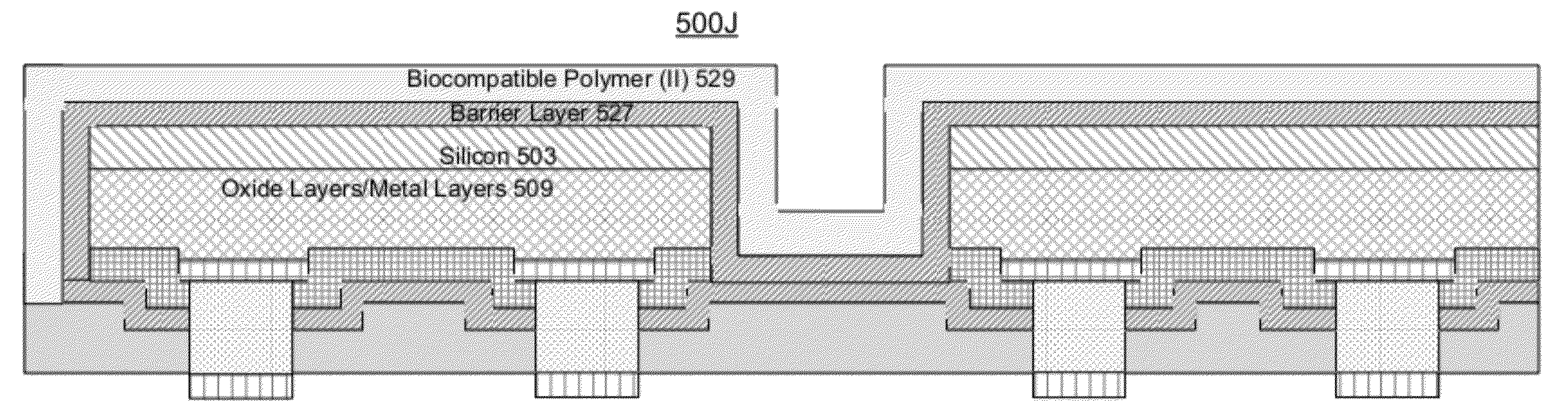
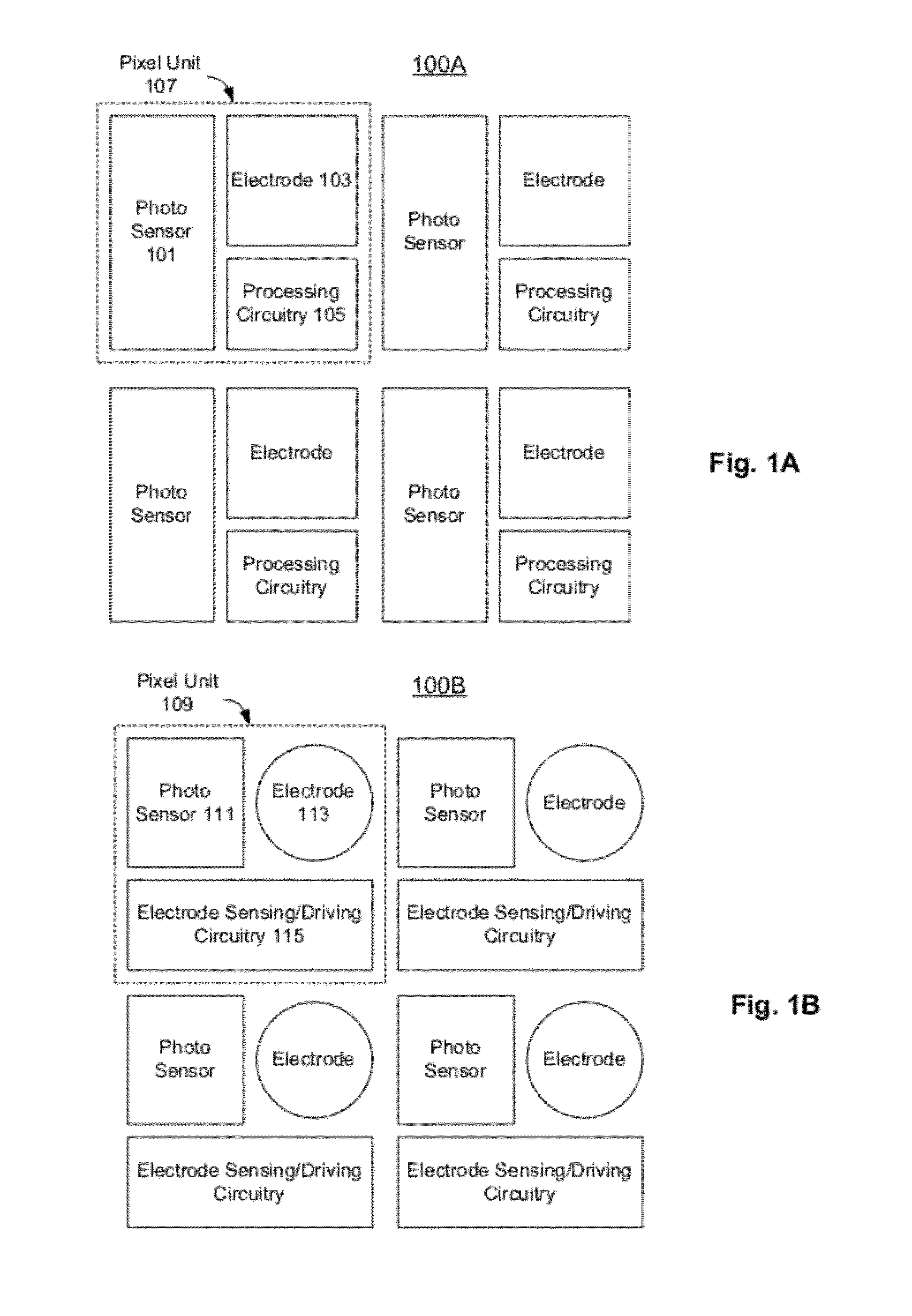
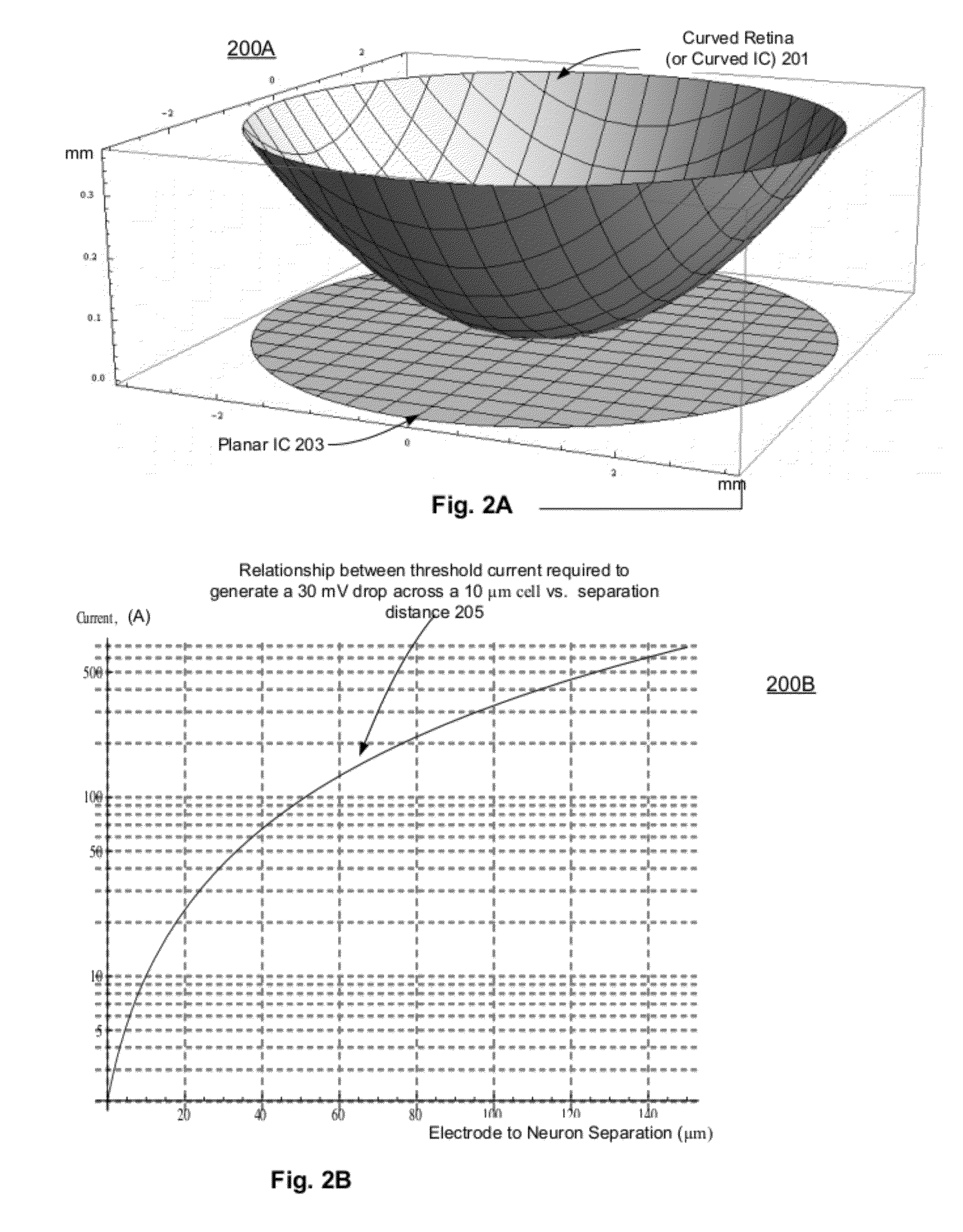
[0034]A flexible IC (integrated circuit) device can integrate an array of “...


PUM


Abstract

Fabrication methods for a flexible device for retina prosthesis are described. Layered structures including an array of pixel units may be formed over a substrate. Each pixel unit may comprise a processing circuitry, a micro electrode and a photo sensor. A first set of biocompatible layers may be formed over the layered structures. The substrate may be thinned down to a controlled thickness of the substrate to allow bending of the substrate to the curvature of a retina. A second set of biocompatible layers may be formed over the thinned substrate. The second set of biocompatible layers may be in contact with the first set of biocompatible layers to form a biocompatible seal wrapping around the device to allow long-term contact of the device with retina tissues. Micro electrodes of the pixel units may be exposed through the openings of these biocompatible layers.

Description

CROSS-REFERENCE TO RELATED APPLICATIONS[0001]The present application is a continuation in part of, and claims the benefit of U.S. patent application Ser. No. 13 / 102,596, filed on May 6, 2011 entitled “RETINA STIMULATION APPARATUS AND MANUFACTURING METHOD THEREOF”, which claims the benefit of Provisional Patent Application No. 61 / 407,229, filed on Oct. 27, 2010, entitled “Retina Prosthesis and the Fabrication Methods of Such”, both of which are hereby incorporated by reference in its entirety into this application.FIELD OF INVENTION[0002]The present invention relates generally to micro devices, and more particularly to flexible integrated circuit devices capable of stimulating neural cells.BACKGROUND[0003]Age-related macular disease (AMD) and the retinitis pigmentosa (RP) disease have been identified as major causes of blindness, especially for senior people worldwide. Retinal prosthesis device offers possible restoration of part of the vision to the blindness. Typically, the device ...

Claims


Application Information

Patent Timeline
Patent Type & Authority Applications(United States)
IPC IPC(8): H01L31/0224
CPCH01L27/14643H01L27/14683A61N1/0543
Inventor FAN, LONG-SHENG
Owner IRIDIUM MEDICAL TECH
Why Eureka
Try Eureka