
Catheter with coronary sinus ostium anchor

a catheter and coronary sinus technology, applied in the field of catheters with coronary sinus ostium anchors, can solve the problems of physician visualization, difficulty in keeping the selection of medical devices stable, and cumbersome current approaches using current fluoroscopically guided techniques

Active Publication Date: 2012-05-03
MEDTRONIC ABLATION FRONTIERS
View PDF23 Cites 16 Cited by
  • Summary
  • Abstract
  • Description
  • Claims
  • Application Information

AI Technical Summary

Problems solved by technology

However, numerous factors render current approaches using current fluoroscopically guided techniques somewhat cumbersome and lengthy for arrhythmia treatment, such as inadequate three-dimensional reconstruction of the left atrium using some currently available technologies, the inability of the physician to visualize particular tissue sites (such as the pulmonary vein ostia), the varying size of the pulmonary veins and thus the pulmonary vein ostia, the difficulty in keeping the selected medical devices stable at the pulmonary vein ostia and other important sites in the left atrium due to the complex geometry of these areas.
Similar difficulties are present for placing cardiac leads or other diagnostic and therapeutic devices within the coronary sinus.
The anatomical structures in and around the coronary sinus itself are not depicted very well by typical fluoroscopic systems since they do not present sufficient contrast to the surrounding anatomical structures.
Moreover, cannulating the coronary sinus may be challenging as a result of an enlarged right atrium, rotation of the heart, or presence of a Thebesian valve (a valve close to the opening of the coronary sinus), and coronary sinus stenosis (occlusion) has also been reported in patients with prior coronary artery bypass surgery, further complicating the intended treatment procedure.
The difficulties described above may result in extended times to complete a designated procedure and potentially expose patients to undesired risks associated with such prolonged procedures.

Method used


Image

  • Catheter with coronary sinus ostium anchor
  • Catheter with coronary sinus ostium anchor
  • Catheter with coronary sinus ostium anchor

Examples


Embodiment Construction

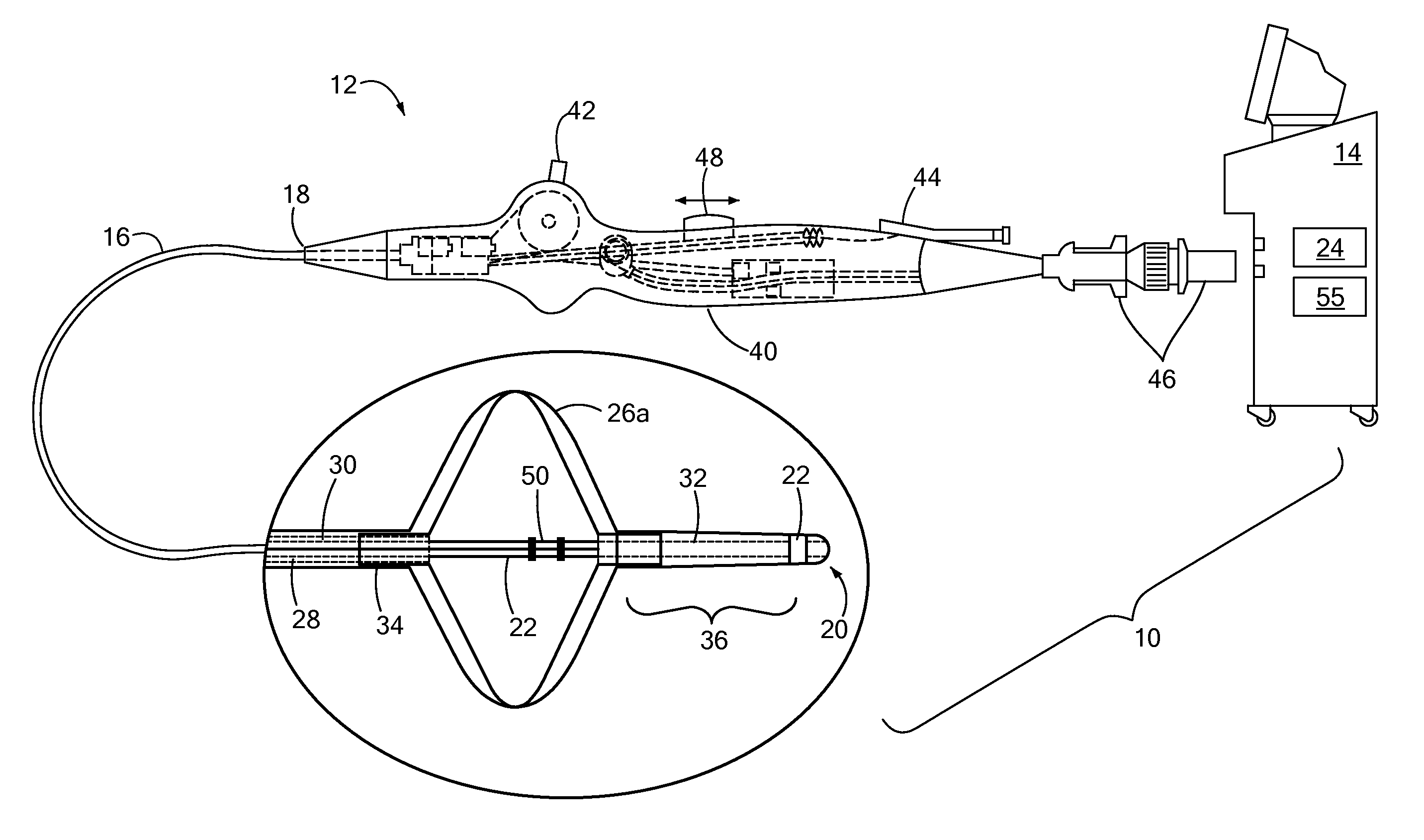
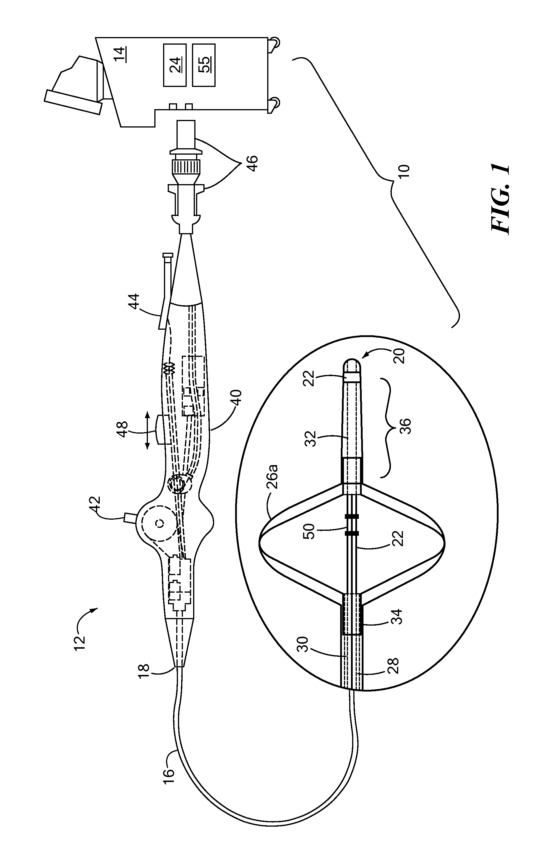
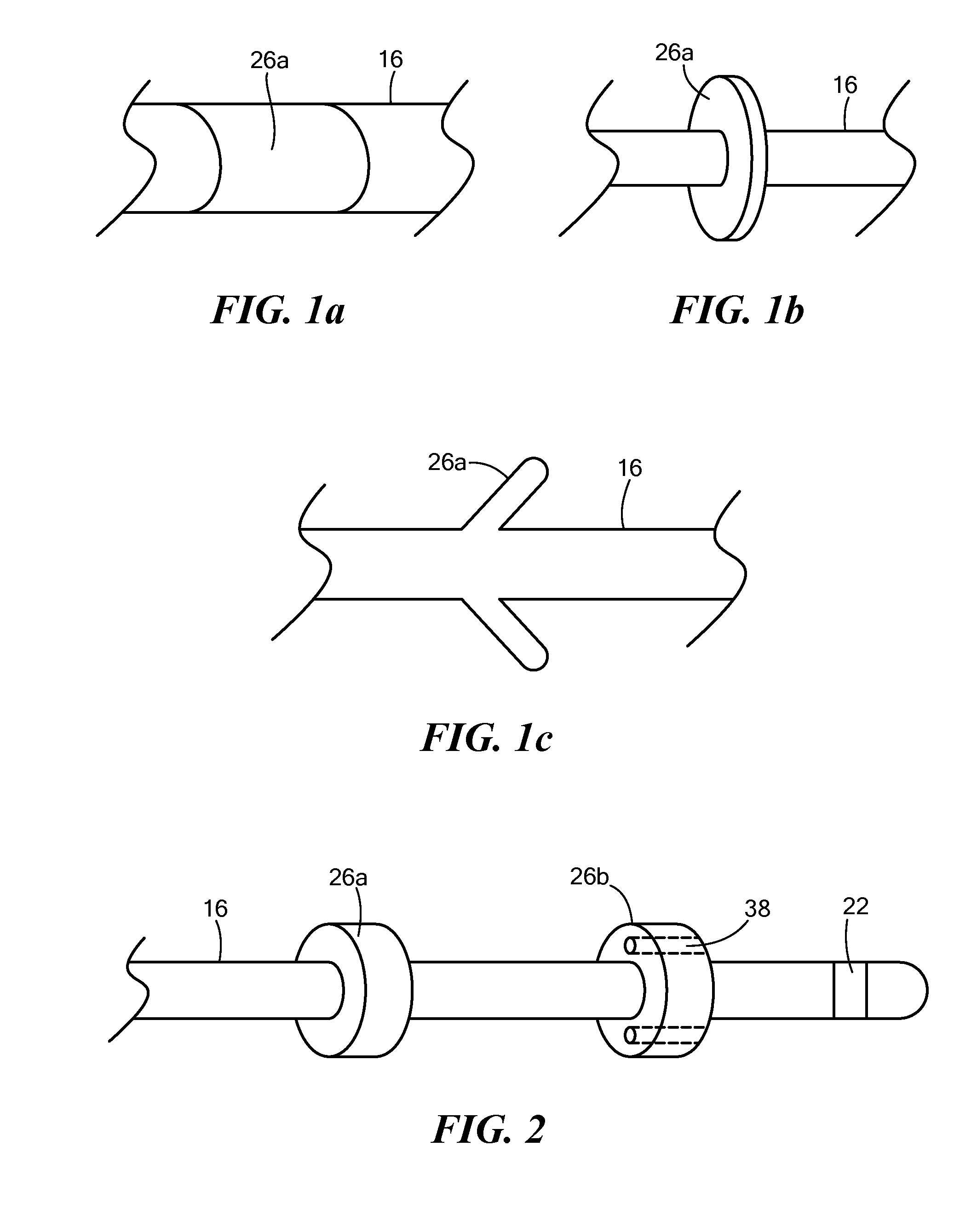
[0021]The present invention advantageously provides methods and apparatus for expeditiously directing and placing medical devices in and around the heart for subsequent diagnosis or treatment. Referring now to the drawing figures in which like reference designations refer to like elements, an embodiment of a medical system constructed in accordance with principles of the present invention is shown in FIG. 1 and generally designated as “10.” Of note, the device components have been represented where appropriate by conventional symbols in the drawings, showing only those specific details that are pertinent to understanding the embodiments of the present invention so as not to obscure the disclosure with details that will be readily apparent to those of ordinary skill in the art having the benefit of the description herein. Moreover, while certain embodiments or figures described herein may illustrate features not expressly indicated on other figures or embodiments, it is understood th...


PUM


Abstract

A method of treating cardiac tissue is provided, including positioning a first chamber of a medical device adjacent an atrial wall; directing a cryogenic coolant into the first chamber; anchoring the first chamber to the atrial wall through cryoadhesion; directing a distal portion of the medical device into the coronary sinus; and positioning a cardiac lead through at least a portion of the coronary sinus with the distal portion. The method may include measuring a temperature of the first chamber; removing the first chamber from the atrial wall once a predetermined threshold temperature of the first chamber is reached; anchoring a second chamber of the medical device to a portion of the coronary sinus; and / or perfusing blood flow through at least a portion of the second chamber.

Description

CROSS-REFERENCE TO RELATED APPLICATION[0001]n / aSTATEMENT REGARDING FEDERALLY SPONSORED RESEARCH OR DEVELOPMENT[0002]n / aFIELD OF THE INVENTION[0003]The present invention relates to methods and systems for cardiac treatment and, more particularly, to systems and methods of use thereof facilitating the positioning of minimally-invasive devices in confined, tortuous physiological areas.BACKGROUND OF THE INVENTION[0004]During a number of interventional procedures related to cardiac treatment, a physician manipulates catheters and / or leads inside the heart chambers and associated vasculature. Two such cardiac procedures include the treatment of an arrhythmia (such as atrial fibrillation) and cardiac pacing. Atrial fibrillation, which refers to an arrhythmia in which the atria (upper chambers of the heart) stop contracting as they fibrillate, is the most commonly experienced heart rhythm abnormality. Both treatment procedures involve directing a catheter or other intravascular device to de...

Claims


Application Information

Patent Timeline
IPC IPC(8): A61B18/02A61B5/05
CPCA61B5/042A61B18/02A61B18/1492A61B2018/00023A61B2018/00214A61B2018/00273A61B2018/00285A61B2018/00755A61B2018/00875A61B2018/00898A61M25/04A61B2090/0811A61B5/283
Inventor MARKOWITZ, H. TOBYTHOMPSON-NAUMAN, AMY E.
Owner MEDTRONIC ABLATION FRONTIERS
Learn More