Self-sealing cannula

a cannula and self-sealing technology, applied in the field of cannula systems, can solve the problems of large burden on health care providers, insufficient blood pumping of the heart, and high cost of treatment, and achieve the effect of reducing the flow “recirculation”

Active Publication Date: 2017-10-26
UNIV OF MARYLAND
View PDF1 Cites 3 Cited by
  • Summary
  • Abstract
  • Description
  • Claims
  • Application Information

AI Technical Summary

Benefits of technology

[0008]The present invention discloses a self-sealing cannula which can be configured as either a double lumen cannula or a single lumen cannula. FIG. 1 shows the self-sealing cannula as a double lumen cannula (DLC). The self-sealing DLC has a drainage cannula and infusion cannula, a self-sealing double umbrella made of wire mesh, and a self-closing iris made of wire mesh. The self-sealing DLC can be used to draw blood directly from the right ventricle through a drainage lumen by a minimally invasive surgery through the pericardium and infuses the blood to the pulmonary artery via an infusion lumen. This configuration can be used for ECMO respiratory su...

Problems solved by technology

Heart failure happens when the heart cannot pump sufficient blood to meet the needs of body.
It creates a major burden on health care providers and is expensive to treat.
Despite the advances in medical care, prognosis with HF remains poor, especially in the advanced stages.
Heart transplantation is limited by the supply of donor organs.
The use of VAD, though increasing, has been limited due to the need for major operative intervention.
Mechanical ventilation is effective for short-term support, yet the sustained tidal volumes and airway pressures often used may damage the lungs.
Thus, only a limited population of patients receives these device-based ...

Method used


Image

  • Self-sealing cannula
  • Self-sealing cannula
  • Self-sealing cannula

Examples


Embodiment Construction

[0030]The invention summarized above may be better understood by referring to the following description, claims, and accompanying drawings. This description of an embodiment, set out below to enable one to practice an implementation of the invention, is not intended to limit the preferred embodiment, but to serve as a particular example thereof. Those skilled in the art should appreciate that they may readily use the conception and specific embodiments disclosed as a basis for modifying or designing other methods and systems for carrying out the same purposes of the present invention. Those skilled in the art should also realize that such equivalent assemblies do not depart from the spirit and scope of the invention in its broadest form.

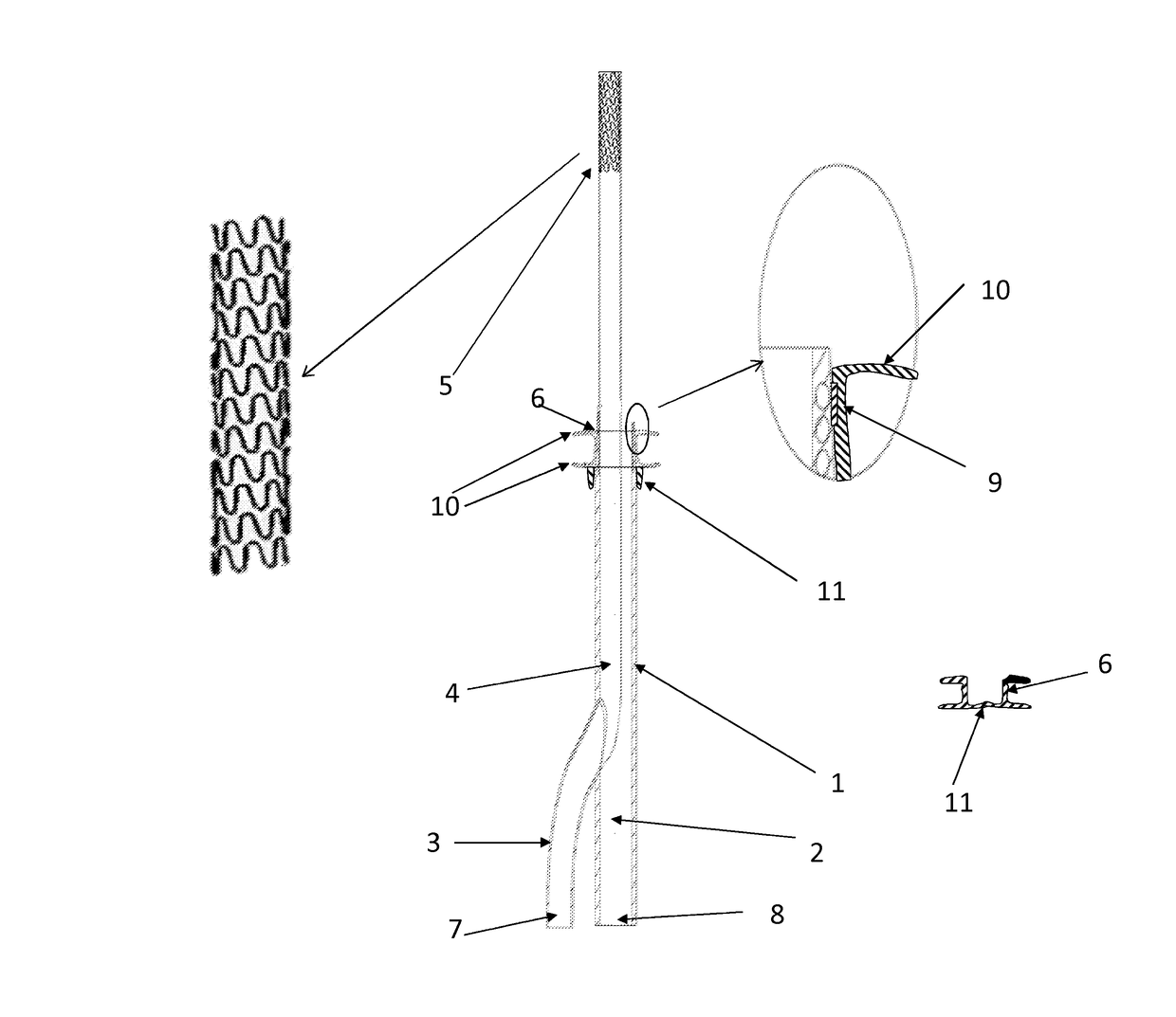
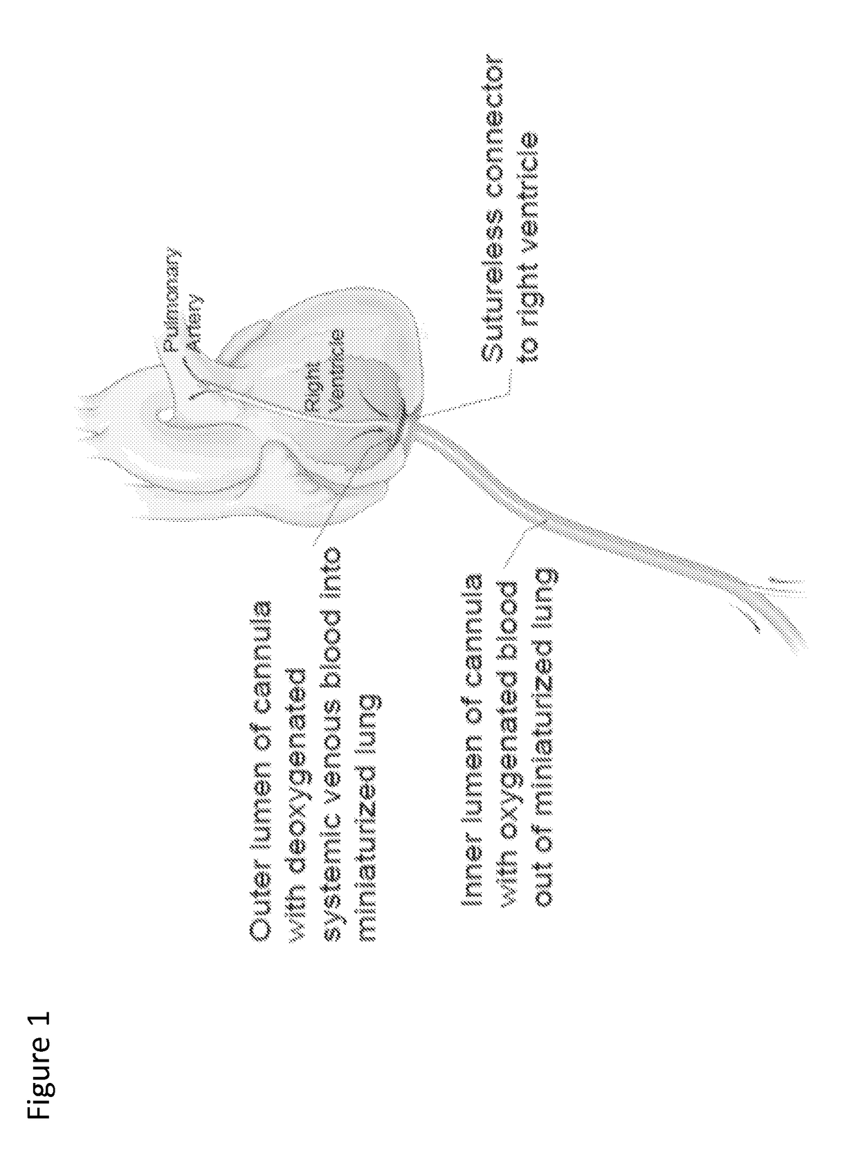
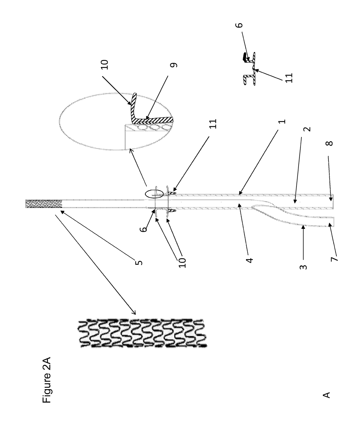
[0031]FIG. 1 is a schematic view of a self-sealing cannula in accordance with aspects of an embodiment of the invention, and more particularly a self-sealing double lumen cannula (DLC) configured to draw blood from the right ventricle through the out...


PUM


Abstract

The present invention discloses a self-sealing cannula and methods of its use. The self-sealing cannula can be minimally invasively placed into the heart for drawing and/or returning blood with a self-sealing function at the interface of the blood access site. The disclosed cannula can be implemented as a single lumen cannula or a double lumen cannula, which can be used with ventricular assist devices for heart support or pump-oxygenators for ECMO and respiratory support. Through a self-sealing mechanism fixed on the ventricular wall or atrial wall, a cannula body is attached to the self-sealing fixture and blood is drawn into the lumen via an external pump and returned to the circulation system through a separate cannula. In the case of the double lumen cannula embodiment, the blood will be drawn into the drainage lumen of the double lumen cannula and returned through an infusion lumen at the desired location. The present invention achieves minimally invasive insertion without surgical sutures to the heart, and allows for optimal drainage of the blood from the heart. With use of the double lumen cannula, it prevents need for multiple cannulation sites, and greatly reduces the blood recirculation. Removal of the cannula is simplified without need for suturing or insertion of a plugging member.

Description

CROSS REFERENCE TO RELATED APPLICATION[0001]This application is based upon co-pending and co-owned U.S. Provisional Patent Application Ser. No. 62 / 079,876 entitled “Self-Sealing Cannula,” filed with the U.S. Patent and Trademark Office on Nov. 14, 2014, the specification of which is incorporated herein by reference.GOVERNMENT LICENSE RIGHTS[0002]This invention was made with government support under Grant Number HL082631 awarded by the National Institutes of Health. The government has certain rights in the invention.FIELD OF THE INVENTION[0003]The present invention relates generally to cannula systems, and more particularly to self-sealing cannula systems for blood draining and / or infusion from and to the circulatory system, and methods of use of such systems.BACKGROUND[0004]The human cardiovascular system serves as the material transport network in the body. It interfaces with the interstitial compartment via diffusion sites throughout the body and exchanges fluids, hormones, electr...

Claims


Application Information

Patent Timeline
IPC IPC(8): A61B17/34
CPCA61B17/3417A61B2017/3419A61B17/3478A61B17/3439A61M1/3659A61B17/34A61B17/3421A61B2017/00247A61B2017/3425A61M60/857A61M60/148A61M60/861A61M60/38A61M60/178A61M60/109A61M60/865A61M60/117A61M60/216A61M60/253
Inventor WU, ZHONGJUNGRIFFITH, BARTLEY P.RAJAGOPAL, KESHAVA
Owner UNIV OF MARYLAND
Why Eureka
Try Eureka