

Spindle condition detection device for machine tool
a technology of condition detection and machine tool, which is applied in the direction of manufacturing tools, program control, instruments, etc., can solve the problem of shortening the operating life of bearings
- Summary
- Abstract
- Description
- Claims
- Application Information
AI Technical Summary
Benefits of technology
Problems solved by technology
Method used
Image

Examples
Embodiment Construction
[0021]Hereinafter, example embodiments of the invention will be described with reference to the accompanying drawings.
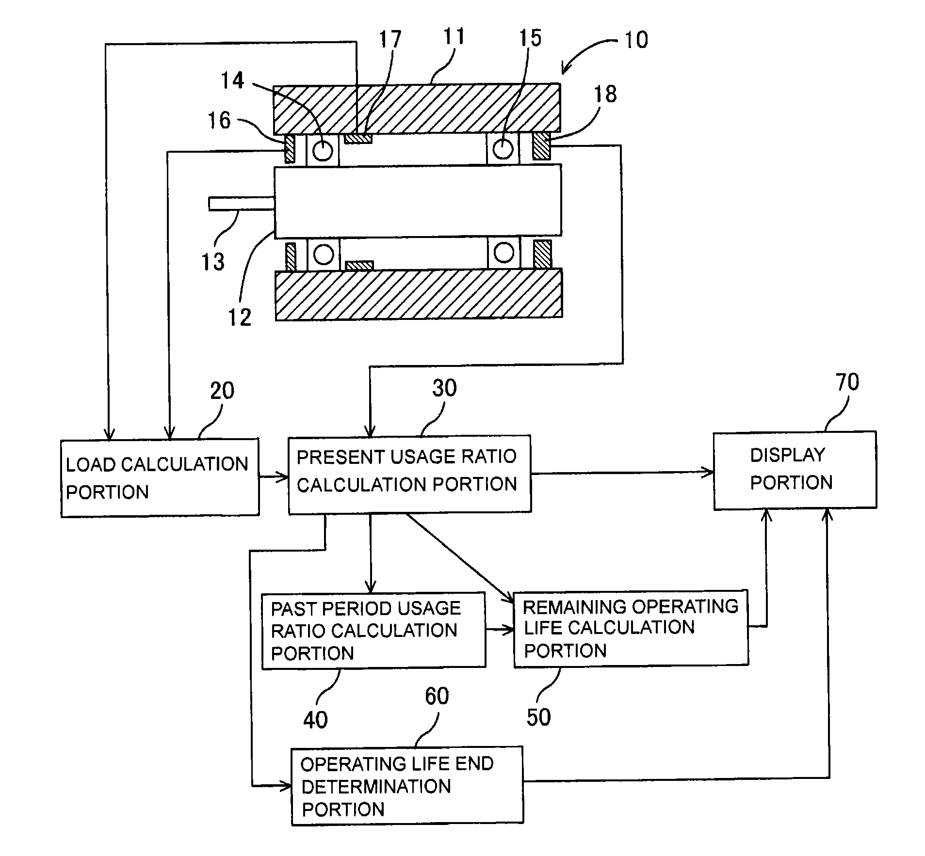
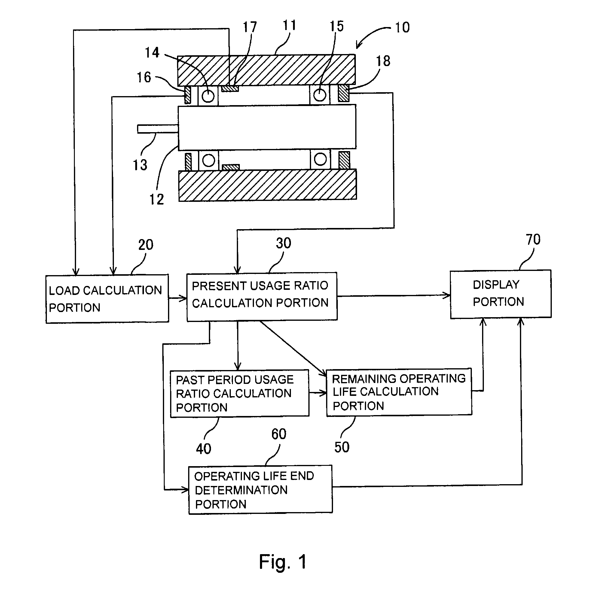
[0022]A spindle condition detection device for a machine tool according to a first example embodiment will be described with reference to FIGS. 1 to 3. As shown in FIG. 1, the spindle condition detection device for a machine tool includes a spindle unit 10, a load calculation portion 20, a present usage ratio calculation portion 30, a past period usage ratio calculation portion 40, a remaining operating life calculation portion 50, an operating life end determination portion 60, and a display portion 70.
[0023]The spindle unit 10 includes a cylindrical housing 11, a spindle 12 that is rotatably supported at a position radially inward of the housing 11, a cutting tool 13 attached at an axial end of the spindle 12, a first bearing 14 and a second bearing 15 that support the spindle 12 such that the spindle 12 is rotatable relative to the housing 11, a radial displacemen...
PUM
| Property | Measurement | Unit |
|---|---|---|
| Fraction | aaaaa | aaaaa |
| Fraction | aaaaa | aaaaa |
| Fraction | aaaaa | aaaaa |
Abstract
Description
Claims
Application Information