
Low calorific fuel combustor for gas turbine

Inactive Publication Date: 2012-05-10
OPRA TECH
View PDF6 Cites 25 Cited by
  • Summary
  • Abstract
  • Description
  • Claims
  • Application Information

AI Technical Summary

Benefits of technology

[0006]In an aspect of the present invention, a can combustor is configured for burning fuels with a low calorific value. The combustor includes a generally cylindrical housing having an interior, a longitudinal axis, an annular inlet for receiving compressed air at one longitudinal housing end with the other longitudinal housing end being closed. Also, a generally cylindrical combustor liner is coaxially disposed in the housing interior, the liner and the housing defining a generally annular flow passage for the compressed air received through the housing inlet, and the interior of the liner defining a combustion zone adjacent the closed housing end and a dilution zone distant the closed housing end. The liner is sized to have an L/D ratio of in the range 1≦L/D≦4, where L is the liner length and D is the liner diameter, and to provide at a rated power, a ratio of the volume V of the combustion zone in meters3 to the fuel energy flow rate Q in the combustor in MJ/sec in the range 0.0026≦V/Q≦0.018. A fuel nozzle assembly is disposed at the closed end, the nozzle assembly being supplied from a source of fuel ha

Problems solved by technology

A principle problem with fuels of a relatively low calorific value, e.g., 25 MJ / kg, or less is the lower flame speed that can adversely affect the completion of combustion, particularly for uneven fuel / air mixtures, thus affecting the local fuel / air ratio in the combustor.
This problem is particularly pronounced in the case of liquid fuels, where the fuel / air mixtures may have large fuel particle (droplet) sizes, which increase the time required to vaporize and burn the particles.
The use of film cooling in these low flame temperature combustors generates high levels of carbon monoxide emissions and eventually creates sediments.

Method used


Image

  • Low calorific fuel combustor for gas turbine
  • Low calorific fuel combustor for gas turbine
  • Low calorific fuel combustor for gas turbine

Examples


Embodiment Construction

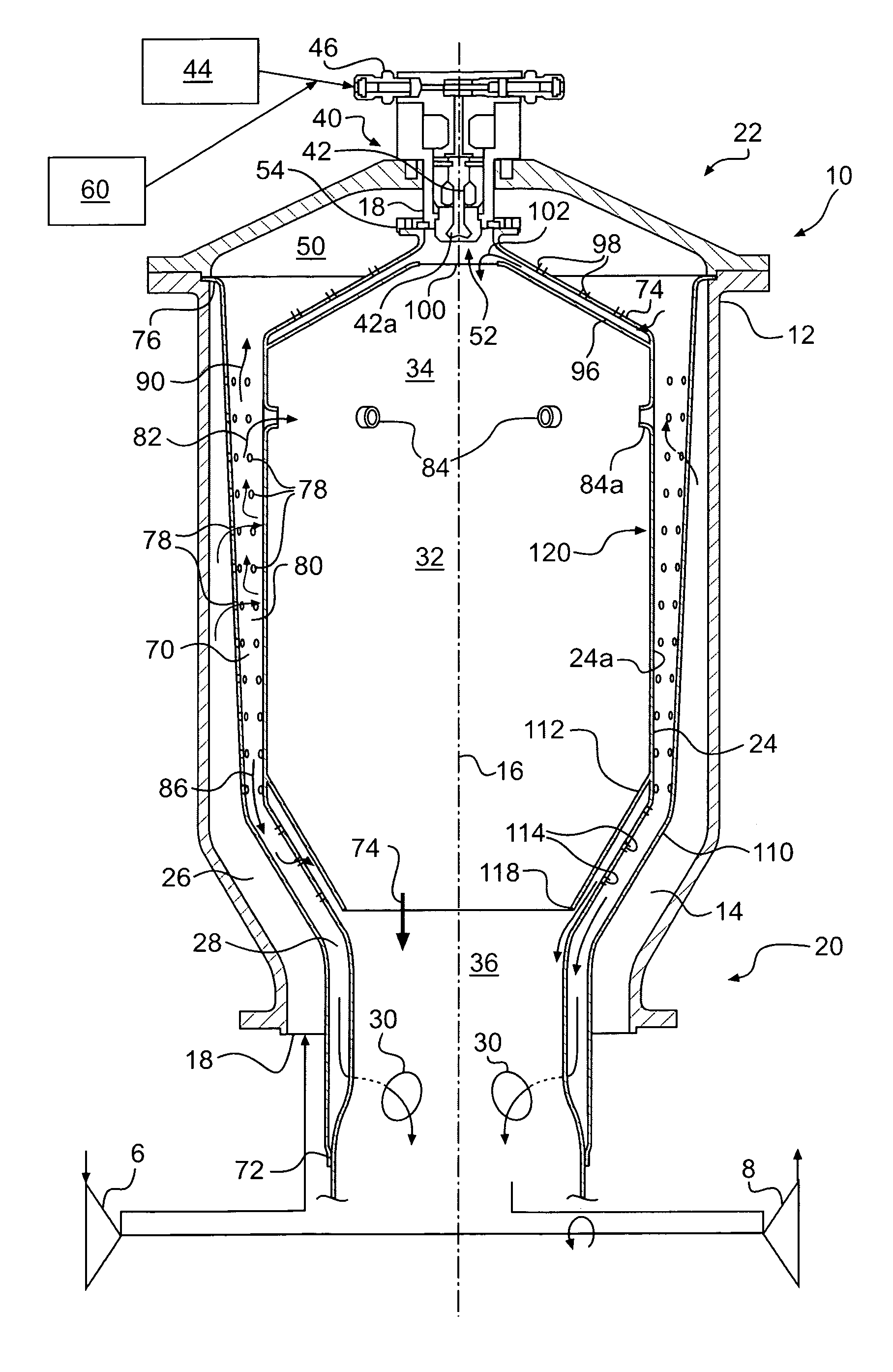
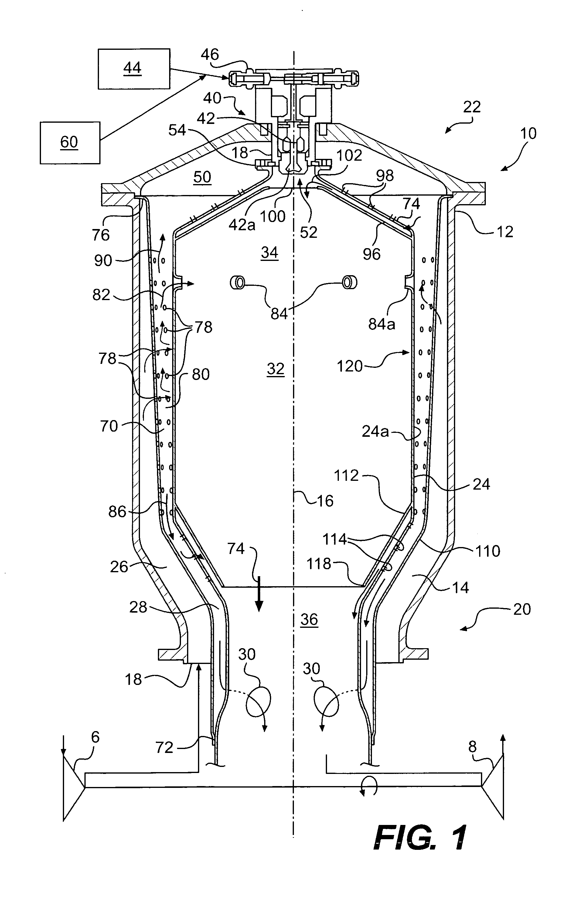
[0010]The can combustor of the present invention, generally designated by the numeral 10 in the figures, is intended for use in combusting fuel having a low calorific value fuel with compressed air from compressor 6, and delivering combustion gases to gas turbine 8, e.g., for work-producing expansion such as in a gas turbine engine. See FIG. 1. Compressor 6 may be a centrifugal compressor and gas turbine 8 may be a radial inflow turbine, but these are merely preferred and are not intended to limit the scope of the present invention, which is defined by the appended claims and their equivalents.

[0011]In accordance with the present invention, as embodied and broadly described herein, the can combustor may include a generally cylindrical housing having an interior, a longitudinal, an annular inlet for receiving compressed air at one longitudinal end, axis with the other longitudinal end being closed. As embodied herein, and with reference to FIG. 1, can combustor 10 includes outer hous...


PUM


Abstract

A low calorific value fuel-fired can combustor for a gas turbine include a generally cylindrical housing, and a generally cylindrical liner disposed coaxially within the housing to define with the housing a radial outer flow passage for combustion air, the liner also defining inner combustion and a dilution zone, the dilution zone being axially distant a closed housing end relative to the combustion zone. A nozzle assembly disposed at the closed housing end includes an air blast nozzle and surrounding swirl vanes. An impingement cooling sleeve coaxially disposed in the combustion air passage between the housing and the liner impingement cools the portion of the liner defining the combustion zone. The combustion liner has an L / D ratio of in the range 1≦L / D≦4, and a ratio of the combustion zone volume (m3) to heat energy flow rate Q (MJ / sec) in the range 0.0026≦V / Q≦0.018.

Description

FIELD OF THE INVENTION[0001]The present invention relates to can combustors for gas turbines. In particular, the present invention relates to low calorific liquid and gaseous fuel-fired, impingement cooled can combustors for gas turbine engines.BACKGROUND OF THE INVENTION[0002]A principle problem with fuels of a relatively low calorific value, e.g., 25 MJ / kg, or less is the lower flame speed that can adversely affect the completion of combustion, particularly for uneven fuel / air mixtures, thus affecting the local fuel / air ratio in the combustor. This problem is particularly pronounced in the case of liquid fuels, where the fuel / air mixtures may have large fuel particle (droplet) sizes, which increase the time required to vaporize and burn the particles.[0003]The achievement of low levels of oxides of nitrogen in combustors is closely related to flame temperature and its variation through the early parts of the reaction zone. Flame temperature is a function of the effective fuel-air ...

Claims


Application Information

Patent Timeline
IPC IPC(8): F02C7/00
CPCF23R3/002F23R3/04F23R3/54F23R2900/03044F23R3/28F23R2900/00002
Inventor BERAN, MARTINKORANEK, MICHALAXELSSON, AXEL LARS-UNO EUGEN
Owner OPRA TECH
Features
  • Generate Ideas
  • Intellectual Property
  • Life Sciences
  • Materials
  • Tech Scout
  • Unparalleled Data Quality
  • Higher Quality Content
  • 60% Fewer Hallucinations
Learn More