
Method for the controlled evaporation of a liquid drop in a microfluidic device

Inactive Publication Date: 2012-05-10
COMMISSARIAT A LENERGIE ATOMIQUE ET AUX ENERGIES ALTERNATIVES
View PDF3 Cites 6 Cited by
  • Summary
  • Abstract
  • Description
  • Claims
  • Application Information

AI Technical Summary

Benefits of technology

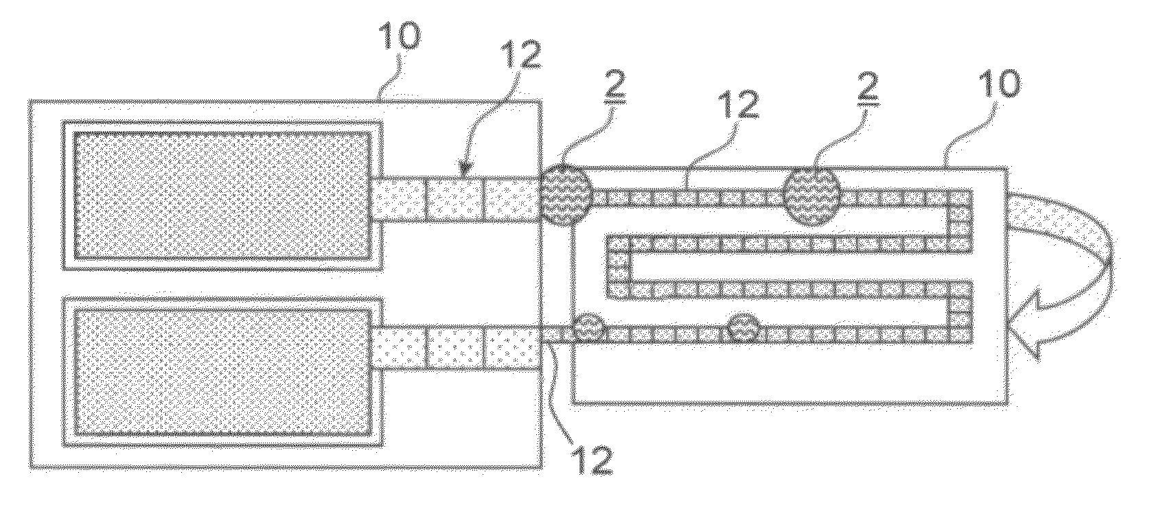
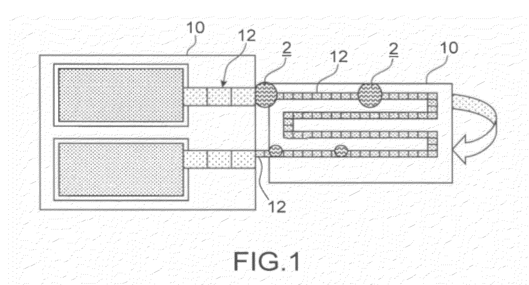
[0029]One object of the invention is to provide a method for the controlled evaporation of a liquid drop located in a closed or confined microfluidic device.
[0035]The contact between the bubble and the drop may not be direct, in that a thin film of a second liquid is present between the bubble and the drop. However, the minimum thickness of this film of second liquid between the “bubble / second liquid” interface and the “drop / second liquid” interface is low enough not to prevent the spontaneous evaporation of the first liquid of the drop in the bubble. The minimum thickness of this film of second liquid is in the order of magnitude, or lower, than the mean diffusion length of molecules of the first liquid of the drop into the second liquid. Thus, the spontaneous evaporation is effective in spite of the presence of this film of second liquid.
[0041]During the evaporation of the drop in the bubble, the bubble and possibly the drop can be heated, so as to increase the evaporation rate of the drop in the bubble.
[0053]Preferably, the means for moving said bubble and / or said drop are able to move the drop and / or the bubble away from each other so as to stop evaporation of the drop in the bubble.

Problems solved by technology

It appears that the method for decreasing the volume by evaporation of the drop and thus for increasing the concentration of analytes possibly present in the drop such as described above is not likely to be used in the closed or confined type microfluidic device.

Method used


Image

  • Method for the controlled evaporation of a liquid drop in a microfluidic device
  • Method for the controlled evaporation of a liquid drop in a microfluidic device
  • Method for the controlled evaporation of a liquid drop in a microfluidic device

Examples


first embodiment

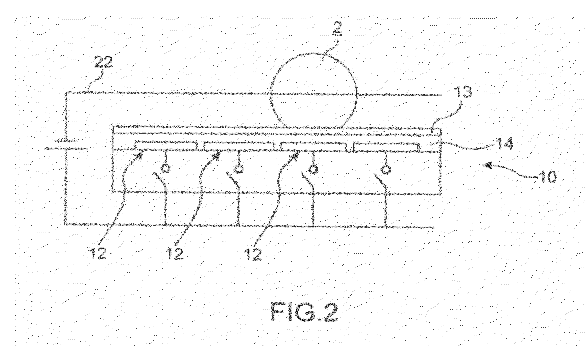
[0044]According to the invention, the drop is brought in contact with the bubble by electrowetting under the effect of an electrical command.

[0045]One of the first and second liquids is then electrically conducting and the other is dielectric. Preferably, the first liquid is electrically conducting and the second liquid is dielectric.

second embodiment

[0046]According to the invention, said drop is brought into contact with the bubble by liquid dielectrophoresis under the effect of an electrical command.

[0047]The first and second liquids thus have dielectric coefficients different from each other.

third embodiment

[0048]According to the invention, said bubble is brought into contact with the drop by thermal expansion of the bubble, by heating it.

[0049]Subsequently to the evaporation step, the bubble can be discharged off the space bounded by said walls through a port provided at either said wall.

[0050]Prior to the evaporation step, the bubble can be introduced between said walls by a port provided at either said wall.

[0051]The invention also relates to a microfluidic device including two walls between which a drop of a first liquid is located surrounded by a second liquid non-miscible with the first liquid.

[0052]According to the invention, it includes means for moving said drop and / or bubble present between said walls, said moving means being capable of bringing said bubble and / or said drop into contact with each other, said contact enabling the drop to evaporate in the bubble.

[0053]Preferably, the means for moving said bubble and / or said drop are able to move the drop and / or the bubble away ...


PUM


Abstract

The invention relates to a method for the controlled evaporation of a liquid drop (2) in a closed or confined type microfluidic device (1), enabling the concentration of analytes possibly present in the drop (2) to be increased.According to the invention, a drop (2) and / or a bubble (4) are brought into contact with each other, said contact enabling the drop (2) to evaporate in the bubble (4).

Description

TECHNICAL FIELD[0001]The present invention relates generally to the field of liquid sample preparation in a microfluidic device, for chemical and / or biological applications.[0002]The liquid sample comes as a drop and is located in a closed or confined type microfluidic device. More precisely, the drop is located between two walls of the device and is surrounded by a liquid non-miscible with it.[0003]The invention is concerned with a method for the controlled evaporation of a liquid drop located in such a microfluidic device.[0004]The drop can include analytes, for example chemical and / or biological particles, such as macromolecules, cells, organites, pathogens, or even intercalating agents.[0005]When such is the case, the invention is also concerned with a method for increasing the concentration of the analytes in the drop.STATE OR PRIOR ART[0006]In numerous fields, it is frequent to attempt to analyse liquid samples, in particular in order to know the concentration of analytes they...

Claims


Application Information

Patent Timeline
IPC IPC(8): B01D1/00B81B1/00
CPCB01L3/502784B01L2200/0678G01N2001/4027B01L2400/0427G01N1/4022B01L2300/089
Inventor RIVAL, ARNAUD
Owner COMMISSARIAT A LENERGIE ATOMIQUE ET AUX ENERGIES ALTERNATIVES
Learn More