Heat dissipation structure

a heat dissipation module and heat dissipation technology, applied in the direction of lighting and heating apparatus, basic electric elements, semiconductor devices, etc., can solve the problems of constant shrinkage of electronic products, heat generation, and inability to meet the requirements of conventional heat dissipation modules, so as to solve the disadvantage of undesirable cooling efficiency of conventional techniques

Inactive Publication Date: 2012-05-10
SUNTENG NEW TECH
View PDF7 Cites 16 Cited by
  • Summary
  • Abstract
  • Description
  • Claims
  • Application Information

AI Technical Summary

Benefits of technology

[0006]The primary object of the present invention is to solve the disadvantage of undesirable cooling efficiency of the conventional technique.

Problems solved by technology

In such developing trends, one of the biggest obstacles is heat generation.
At present, the most common cause of malfunction or damage of electronic elements is poor heat dissipation that results in overheating.
However, the size of electronic products is shrunk constantly.
Conventional heat dissipation modules cannot meet this requirement.
Overheated problem has become a bottleneck of electronic element technology development.
This not only enhances the reliability of an electronic product, but also prolongs the lifespan thereof.
But the air fan employs compulsory convection for cooling and creates many problems, such as power consumption, noise generation and shorter lifespan.
The aforesaid conventional technique has a drawback that the cooling capability thereof is restricted by the volume in the heat pipe.
Moreover, if the heat pipe is applied to electronic elements with super high speed, it will generate a greater amount of heat during operation and cannot achieve the cooling requirement.

Method used


Image

  • Heat dissipation structure
  • Heat dissipation structure
  • Heat dissipation structure

Examples


Embodiment Construction

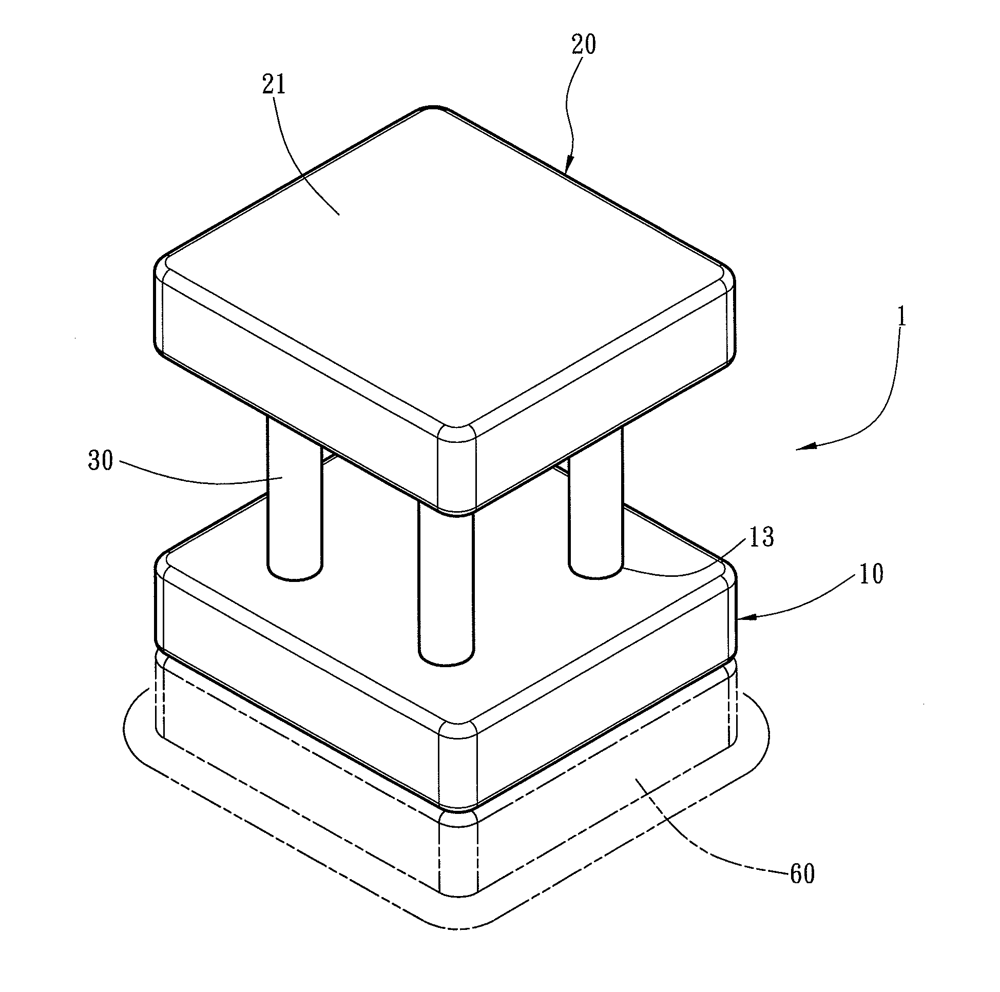
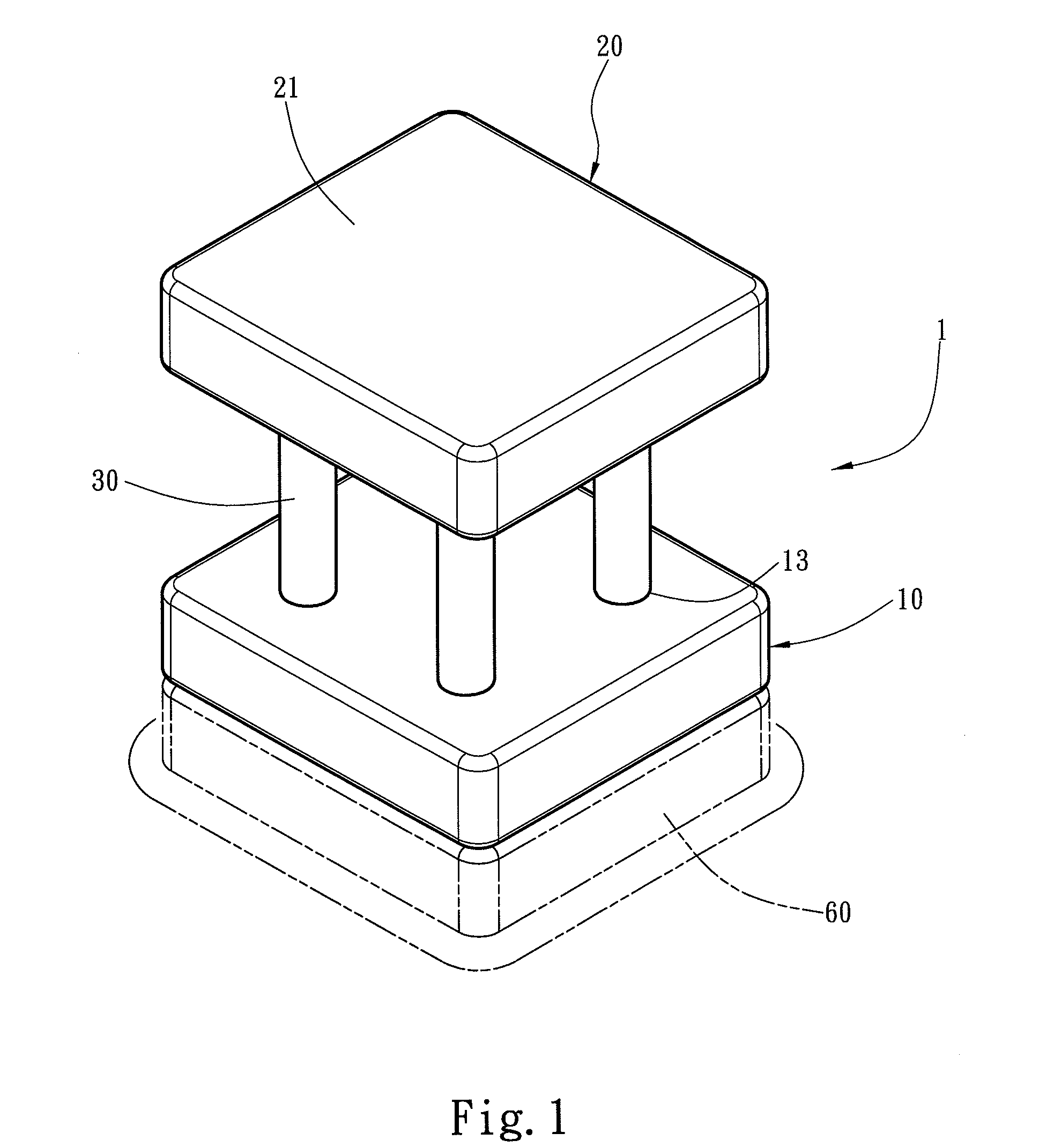
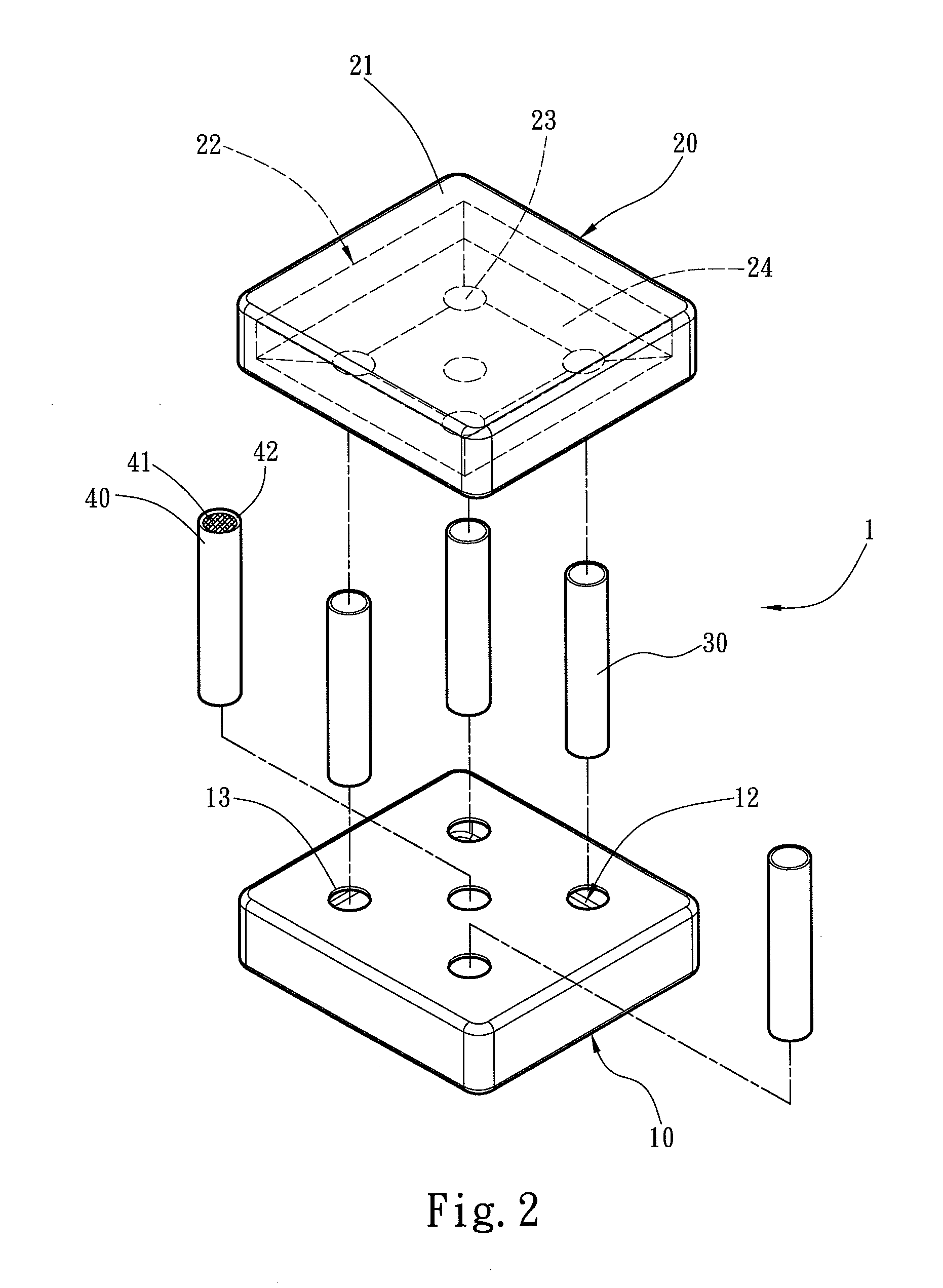
[0015]Please refer to FIGS. 1 and 2, the present invention aims to provide an improved heat dissipation structure 1 mainly adopted on an electronic element 60 to dissipate heat thereof.

[0016]The heat dissipation structure 1 includes a heat absorber 10, a heat sink 20 and a plurality of first conduits 30 bridging the heat absorber 10 and heat sink 20. The heat absorber 10 is installed on the surface of the electronic element 60 to absorb heat generated thereon. The heat absorber 10 is a hollow casing containing a first chamber 12. The heat sink 20 also is a hollow casing containing a cooling surface 21 and a second chamber 22 to perform heat exchange. The heat absorber 10 and heat sink 20 have respectively a plurality of first coupling orifices 13 and second coupling orifices 23 to couple with the first conduits 30. Thus forms the main structure of the invention.

[0017]Referring to FIGS. 3A and 3B, the heat absorber 10 is mounted onto the electronic element 60 with a contact surface 1...


PUM


Abstract

A heat dissipation structure mounted onto an electronic element to dissipate heat. The heat dissipation structure includes a heat absorber connected with the electronic element and a heat sink. The heat absorber has a hollow first chamber to hold a working fluid. The heat absorber and heat sink are interposed by a plurality of first conduits. When the heat absorber absorbs heat generated by the electronic element through a contact surface, the working fluid held therein is vaporized into vapor. The vapor enters a second chamber of the heat sink through the first conduits and performs heat exchange with a cooling surface of the heat sink to be converted into the working fluid again. The working fluid is conveyed via a capillary structure in the second conduit to the first chamber to form a thermal cycle. The structure of the invention is simpler and can rapidly absorb and dissipate heat.

Description

FIELD OF THE INVENTION[0001]The present invention relates to a heat dissipation structure and particularly to an improved heat dissipation structure having a capillary structure.BACKGROUND OF THE INVENTION[0002]Advance of technology brings great benefits to people's life and constantly enhances functionality and performance of electric appliances. For instance, high-level electronic products stressed on processing speed and reliability such as server and workstation, and even personal computer and notebook computer, have promoted higher performance and speed requirement for CPU. In such developing trends, one of the biggest obstacles is heat generation. At present, the most common cause of malfunction or damage of electronic elements is poor heat dissipation that results in overheating. Heat is mainly generated by active elements such as transistors in IC during processing. The more transistors included in chips, the greater heat generated. However, the size of electronic products i...

Claims


Application Information

Patent Timeline
Patent Type & Authority Applications(United States)
IPC IPC(8): F28D15/00
CPCF28D15/0266H01L23/427H01L2924/0002H01L2924/00
Inventor WANG, CHING-TU
Owner SUNTENG NEW TECH
Why Eureka
Try Eureka