Traction control system and method

a technology of traction control and control system, applied in the direction of braking system, position/direction control, locomotive, etc., can solve the problems of wheel slippage, difficult to find the right throttle setting to achieve optimum creep, and the problem of slipping and sliding occurs, etc., to achieve the effect of small diameter/circumferen

Inactive Publication Date: 2012-05-10
SCHAFFLER INT PTY
View PDF5 Cites 13 Cited by
  • Summary
  • Abstract
  • Description
  • Claims
  • Application Information

AI Technical Summary

Benefits of technology

[0013]Embodiments of the present invention relate to traction control systems for wheeled vehicles. Through extensive research and testing, the present inventor has found that wheel wear in vehicles, such as locomotives, can vary from wheel to wheel depending on factors such as wheel location, direction of travel, vehicle loading and the like. It has been found that slip and slide is more likely to occur on wheels that are worn and thus have a smaller diameter / circumference than less worn wheels due to the small margin at which optimum creep is obtained.
[0014]The traction control system according to the present invention advantageously compensates for traction and braking force differences exerted on individual wheels of the vehicle caused through wheel wear.

Problems solved by technology

Typically, slip and slide occur when the forces applied to the wheels of the locomotive are larger than the maximum friction force between the wheel and rail surfaces.
As persons skilled in the art will appreciated, finding the right throttle setting to achieve optimum creep can be difficult to achieve.
In many instances the locomotive operator will apply too much throttle resulting in wheel slip and have to subsequently ease off the throttle to maintain fraction.
Conversely, during braking, too much braking force can be instructed by the locomotive controller, resulting in wheel slide.

Method used


Image

  • Traction control system and method
  • Traction control system and method
  • Traction control system and method

Examples


Embodiment Construction

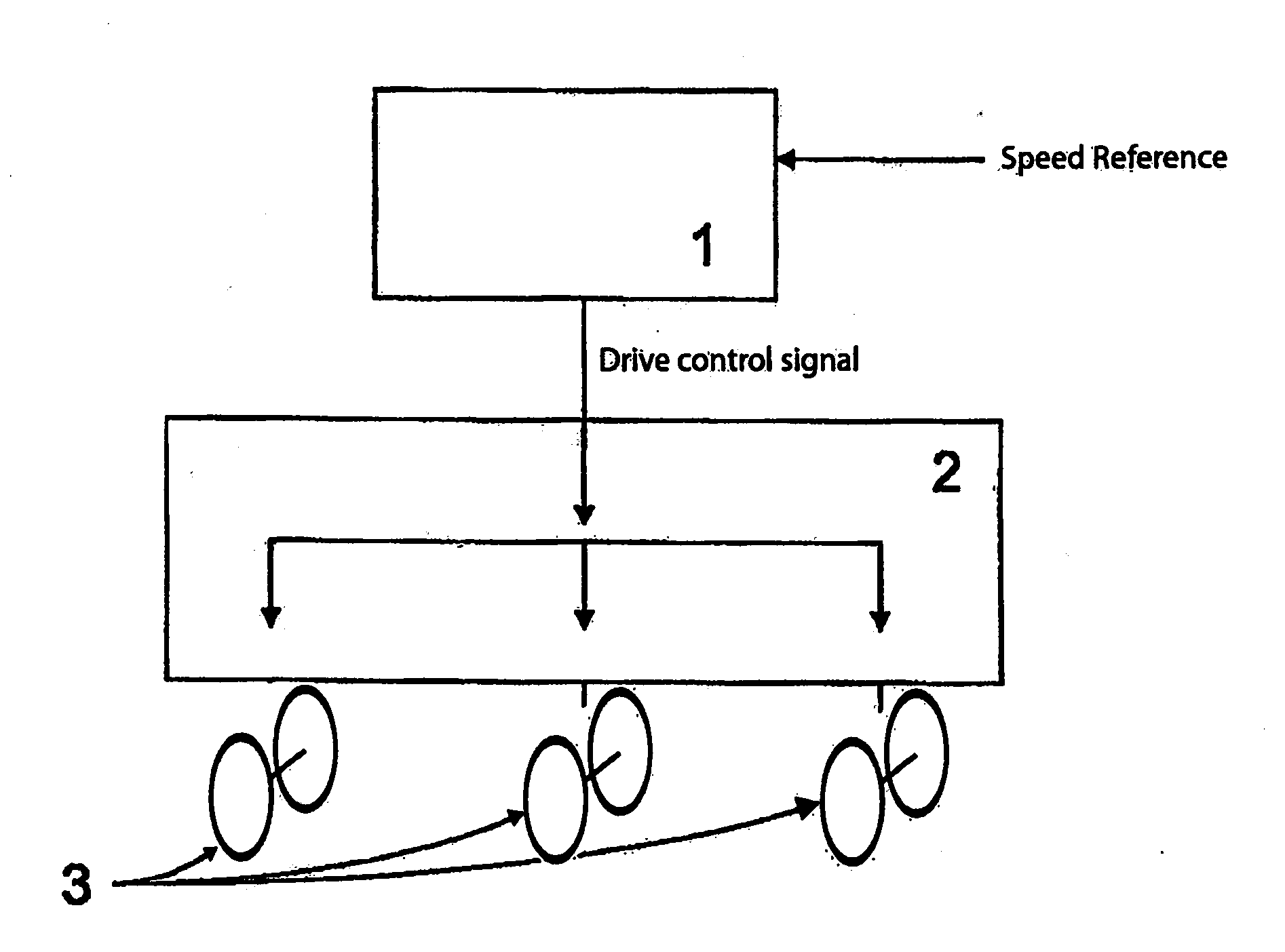
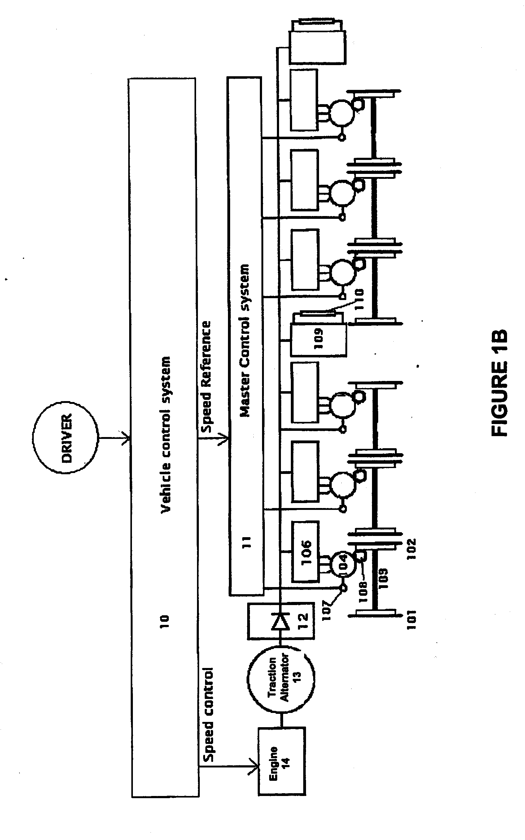
[0075]The present invention relates to traction control systems and methods which advantageously compensate for different traction and braking forces experienced by individual wheels of a vehicle having varying sizes. In an embodiment, this is achieved by measuring the individual wheel diameters relative to a reference wheel diameter and taking those measurements into account when controlling power to each individual wheel, so as to avoid wheel slip and slide.

[0076]Embodiments of the present invention will hereafter be described in the context of a traction control system and method for an AC locomotive. However, it will be understood by persons skilled in the art that embodiments are equally applicable to any wheeled vehicle and should not be seen as limited to the particular embodiment described herein. For example, the present invention could equally be used for controlling traction on a grader, or any other vehicle where varying wheel diameter may cause slip and slide to occur.

[...


PUM


Abstract

A method for providing traction control on a wheeled vehicle involves receiving a speed reference signal. A variance in wheel size between a first and at least one other wheel of the vehicle is determined. Lastly, a drive control signal operable to control power to each of the first and at least one other wheel is output, the drive control signal being based on the speed reference signal and determined variance in wheel size and operable to provide that a tractive force exerted by each of the wheels on a corresponding surface during traction and/or braking is substantially similar.

Description

FIELD OF THE INVENTION[0001]The present invention relates generally to a traction control system and method and more particularly, but by no means exclusively, to a system and method for providing traction control for a locomotive.BACKGROUND OF THE INVENTION[0002]In many vehicular applications it is desirable to be able to effectively control the power applied to a drive train, so as to avoid slip and slide of the vehicle's wheels. This is particularly the case for rail based vehicles, such as locomotives, where it is important that the vehicle be able to accelerate up to operating speed in minimal time and to decelerate rapidly to a stop condition.[0003]Locomotives and other rail based vehicles obtain traction and braking forces by means of friction between the wheel surface and the rail surface. Typically, slip and slide occur when the forces applied to the wheels of the locomotive are larger than the maximum friction force between the wheel and rail surfaces. Slip occurs when for...

Claims


Application Information

Patent Timeline
Patent Type & Authority Applications(United States)
IPC IPC(8): G06F7/00
CPCB60L3/10B60L7/00B60T8/1705B60L2200/26B61C15/08Y10S903/902B60T8/175B61L3/006B61L25/021
Inventor SCHAFFLER, BERNARDZHOU, REN
Owner SCHAFFLER INT PTY
Why Eureka
Try Eureka