Packet-level erasure protection coding in aggregated packet transmissions

a packet transmission and protection coding technology, applied in the field of aggregated packets, can solve the problems of substantial protocol processing overhead and reduce transmission rates, and achieve the effect of reducing transmission rates and reducing protocol processing overhead

Inactive Publication Date: 2012-05-10
QUALCOMM INC
View PDF3 Cites 70 Cited by
  • Summary
  • Abstract
  • Description
  • Claims
  • Application Information

AI Technical Summary

Benefits of technology

[0006]In a first aspect, an aggregated packet includes a plurality of packets and one or more EC-Blocks (Error Correction Blocks). The EC-Blocks contain error correction coding information generated from the plurality of packets. In general, these EC-Blocks may be generated using various types of encoding methods, such as Hamming codes, Reed-Solomon codes, BCH codes, low-density parity-check (LDPC) codes, and Fountain codes. The aggregated packet is communicated such that the receiver does not need to return an acknowledgement for each packet, but rather returns a single block acknowledgement for the entire aggregated packet. In one example, the aggregated packet is an IEEE 802.11n compliant Aggregated-MPDU (A-MPDU) that contains a plurality of MPDUs and one or more EC-Blocks. A Fountain coding scheme, such as for example a Raptor forward error correction coding scheme or a RaptorQ forward error correction coding scheme, is used to generate the error correction coding information from the plurality of MPDUs. The resulting error correction coding information is broken into sections such that a first portion is included in a first EC-Block of the A-MPDU, such that a sec

Problems solved by technology

In a communication system such as a WiFi communication system compliant with the Institute of Electrical and Electronic Engineers (IEEE) 802.11n standard, the communication of MAC (Medium Access Control) Protocol Data Units (MPDUs) can involve substantial protocol processing overhead

Method used


Image

  • Packet-level erasure protection coding in aggregated packet transmissions
  • Packet-level erasure protection coding in aggregated packet transmissions
  • Packet-level erasure protection coding in aggregated packet transmissions

Examples


Embodiment Construction

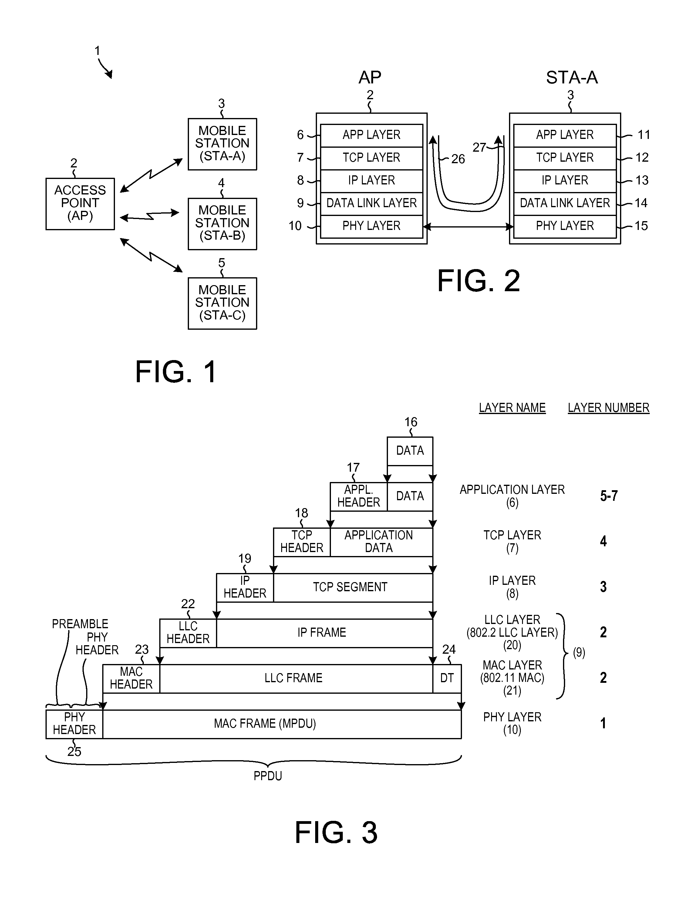
[0033]FIG. 1 is a diagram of an IEEE 802.11 wireless communication system 1 employing an Access Point device (AP) 2, a first mobile station device (STA-A) 3, a second mobile station device (STA-B) 4, and a third mobile station device (STA-C) 5. Each station device communicates with the access point using a set of protocols. The protocol processing functionality on the AP is referred to as a stack of protocol processing layers. In the example of FIG. 1, the layers of the stack include an application layer 6, a TCP layer 7, an IP layer 8, a data link layer 9, and a physical layer 10. Similarly, the protocol processing functionality on the STA is referred to as a stack of protocol processing layers. The layers include an application layer 11, a TCP layer 12, an IP layer 13, a data link layer 14, and a physical layer 15.

[0034]FIG. 2 is a diagram showing the protocol stacks in AP 2 and in STA-A 3. The stacks are implemented using combinations of hardware and software. If AP 2 is to send ...


PUM


Abstract

In a first aspect, an aggregated packet (A-MPDU) includes packets (MPDUs) and EC-Blocks (Error Correction Blocks) containing error correction coding information. A transmitter uses a Fountain coding scheme (for example, Raptor or RaptorQ) to generate the error correction coding information from the MPDUs. If a receiver detects an error in a received MPDU, then the receiver uses the error correction coding information from the EC-Blocks to correct the error. In a second novel aspect, a determination is made as to whether a change in error rate is more likely due to collisions or to a low SNR. If the determination is that the change is due to collisions then the MCS index is adjusted to restore a target error rate, whereas if the determination is that the change is due to a low SNR then the number of EC-Blocks per A-MPDU is adjusted to restore the target error rate.

Description

CROSS-REFERENCE TO RELATED APPLICATION[0001]This application claims the benefit under 35 U.S.C. §119 of Provisional Application Ser. No. 61 / 411,777, filed Nov. 9, 2010, entitled “PACKET-LEVEL ERASURE PROTECTION CODING IN AGGREGATED PACKET TRANSMISSIONS”, which is expressly incorporated herein by reference in its entirety for all purposes.BACKGROUND INFORMATION[0002]1. Technical Field[0003]The present disclosure relates to aggregated packets, and more particularly in one example to the including of Fountain-encoded error correction coding information into an aggregated packet such an A-MPDU in an IEEE 802.11 communication.[0004]2. Background Information[0005]In a communication system such as a WiFi communication system compliant with the Institute of Electrical and Electronic Engineers (IEEE) 802.11n standard, the communication of MAC (Medium Access Control) Protocol Data Units (MPDUs) can involve substantial protocol processing overhead due to a receiver of MPDUs having to return ei...

Claims


Application Information

Patent Timeline
IPC IPC(8): H03M13/05G06F11/10
CPCH04L1/0003H04L1/0009H04L1/0019H04L1/1819H04L1/0057H04L1/0065H04L1/008H04L1/0041Y02D30/50H04L1/0061H04L1/0078H04L1/1825
Inventor TAGHAVI NASRABADI, MOHAMMAD HOSSEINSAMPATH, HEMANTHMERLIN, SIMONEABRAHAM, SANTOSH P.VERMANI, SAMEERTANDRA, RAHUL
Owner QUALCOMM INC
Why Eureka
Try Eureka