
Fire-barriers for straight-line and intersecting expansion-spaces having male and female coupling-ends

a technology of expansion space and fire-barriers, which is applied in the direction of construction, building components, construction materials, etc., can solve the problems of presenting a major risk, affecting construction efficiency, and affecting construction efficiency, so as to reduce the time it takes to install the barriers and the health risks, and increase the worker's insurance. , the effect of reducing the cost of construction

Active Publication Date: 2012-05-17
INPRO CORP
View PDF20 Cites 79 Cited by
  • Summary
  • Abstract
  • Description
  • Claims
  • Application Information

AI Technical Summary

Benefits of technology

[0010]The present Inventor recognized that the manufactured on-site barriers that were being used to fill the expansion-space-intersecting-spaces may likely not pass the cycle and fire tests. One problem with constructing barriers on-site is that they are constructed from parts of sectioned straight-line barriers. However, when any tested, rated, and certified fire-barrier is modified in any way, it immediately loses its certification and rating. To be able to use the on-site constructed barriers, builders must have their engineers certify the barriers. That does not mean, however, that these on-site constructions are capable of passing the extension / compression and fire-test, which could result in a building and its occupants being at a serious risk in the event of a fire. Moreover, in order to fit an especially long straight-line section several barriers or sections of barriers must be spliced together. The present inventor feared that spliced seams between sections of straight-line barriers and between straight-line barriers and expansion-space-intersecting fire-barriers could allow hot air, smoke, toxic gases, and fire to travel throughout the expansion-joint-spaces of a building. Furthermore, as the connections formed during the requiring splicing procedures, are sometimes simply staples, and as spliced barriers have been known to be installed by non-specialists, they may not stand up to even relatively mild stresses of tension / compression and / or shear movements. Furthermore, the present Inventor realized that not only is on-site assemblage and splicing of fire-barriers inherently an unsafe practice, it is time-consuming and often the barriers so produced often require more than one installation person, which all adds significantly to the total construction cost. Moreover, he realized that on-site assembling could and likely did expose workers hands and arms to being cut by the thin sheets of stainless steel that are often a part of a fire-barrier, and that whenever the installers would cut the fiber glass (or similar material) blankets breathable sized fibers are introduced into the workplace atmosphere resulting in increased worker's insurance. The present inventor recognized how beneficial to the worker, the contractor, and the building owner it would be to have fire-barriers, both those for fitting into straight-line expansion spaces and those for fitting into intersecting-expansion-spaces, pre-assembled with male and female coupling-ends that provide not only for one-step drop-in installation of all of the styles of barriers into their respective expansion spaces, but for self-coupling of each barrier to its adjacent barrier as part of the drop-in installation while avoiding any gaps such are seen in other barriers. Such an improved product would greatly reduce both the time it takes to install the barriers and the health risks, thus cutting the cost of construction and worker's liability insurance.
[0011]Thus, the present Inventor recognized that without better fire-barriers, life and property would continue to be at increased risk whenever there was a fire in a building mandated to have expansion-joint spaces. He contemplated that to be able to have code-tested and rated geometrically complex intersection-space fitting fire-barriers, each barrier should be designed and constructed to have continuous-piece construction, and to have no openings or gaps through the barrier so as to prevent providing a pathway for the travel of smoke, fire, or gases. The present inventor also believed that he could design ways to connect adjacent barriers to each other to avoid the gaps that exist in the designs currently used, so that an entire family of straight-line and expansion-space-intersecting fire-barriers could all be tested, rated, and certified by an approved testing agency.
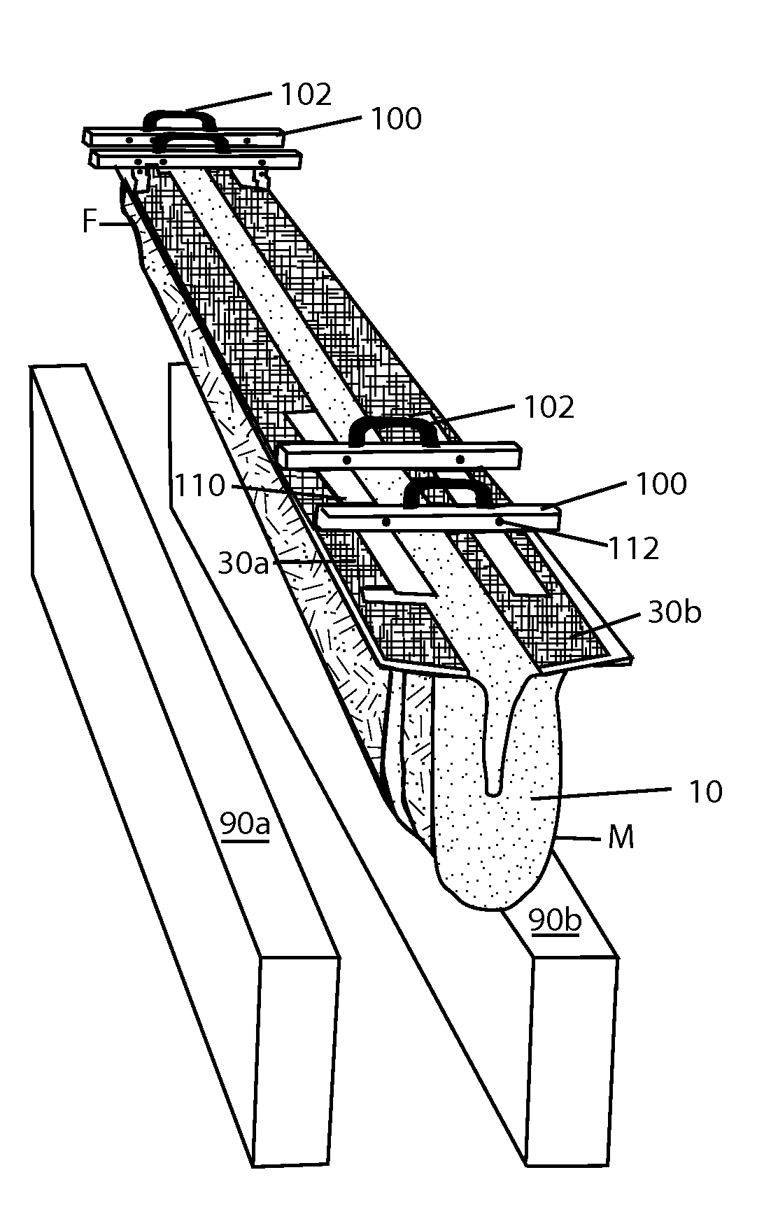
[0013]The fire-barriers of the present invention are unique in several ways. One point of novelty is that both intersection-space and straight-line barriers are available as tested, rated, and certified pre-assembled barriers, all having female / male coupling-ends. One example, provided herein as a favored embodiment, is an L-shaped fire-barrier (also referred to as a horizontal / vertical barrier) having male / female connecting ends that can be installed in a one-step, drop-in process into a L-shaped intersecting-expansion-joint-space created by the convergence of the expansion spaces between two building structures, such as a floor and a wall or a wall and a ceiling. The L-shape, as illustrated, however, is only one of a large number of possible configurations that can be embodied with the principles of the present invention. The invention contemplates one-piece, male / female coupling-ended barriers shaped for fitting into cross-shaped, T-shaped, and L-shaped intersecting-expansion-spaces. It should be noted that L-shaped barriers may also be manufactured having additional horizontal / horizontal arms. All of the barriers manufactured according to the inventive principles described herein are available having female connections, male connections, or both, depending on the specific configuration of the intersecting-expansion-spaces. The interdigitating female / male coupling-ends taught herein require only a bead of fire-resistant caulk to be applied over the seams between the two coupled barriers. No cutting or stapling, or other attachments are required by the overlapping coupling-ends. Once barriers are coupled there are no gaps in the coupled areas which is due to the fact that there is no extension of the outer protective cloth along its long axis, so as to provide for the protective cloth to cover the insulation blanket layers throughout the male / female interdigitating area. Not having such an extended length of protective cloth folded over the male or female shaped ends prevents the creation of a gap where the extended protective cloth is folded over the insulation blanket layers and so must “bend” around the offset layer(s) of insulation blanket. In the barriers of the present invention, one layer of refractory material is laid flat against its adjacent layer. Thus there are only flat layers adjacent to flat layers, that is, all layers are laid-flat, and there is no folding or pleating with a layer. Thus, there need be no holes punched into the insulation blankets and protective cloth to bring them close together and to attach them, and following, there are no holes through the totality of the overlapping sections in the coupled areas, as no wire or other attachment means goes through the overlapped areas so as to attach the overlapping female / male portions to each other. Additionally, each style of male and female ended fire-barrier is supplied with its own optional reusable installation tool that provides for even quicker, easier, and safer one-step, drop-in installation of both the pre-assembled, female and male ended multi-directional / multi-dimensional and straight-line fire-barriers. The installation tools are not only reusable, but also easily and rapidly size-adjustable for use with differently sized versions of the same style barriers.

Problems solved by technology

While expansion-spaces improve the life-time integrity of structures, they present a major risk in the event of a fire because the channels created by the expansion-spaces act as chimney flues providing pathways for gases, flame, and smoke to spread rapidly throughout the structure.
One problem with constructing barriers on-site is that they are constructed from parts of sectioned straight-line barriers.
However, when any tested, rated, and certified fire-barrier is modified in any way, it immediately loses its certification and rating.
That does not mean, however, that these on-site constructions are capable of passing the extension / compression and fire-test, which could result in a building and its occupants being at a serious risk in the event of a fire.
Furthermore, as the connections formed during the requiring splicing procedures, are sometimes simply staples, and as spliced barriers have been known to be installed by non-specialists, they may not stand up to even relatively mild stresses of tension / compression and / or shear movements.
Furthermore, the present Inventor realized that not only is on-site assemblage and splicing of fire-barriers inherently an unsafe practice, it is time-consuming and often the barriers so produced often require more than one installation person, which all adds significantly to the total construction cost.
These barriers suffer not only from dangerous gaps caused by the different lengths of protective cloth and of insulation blanket, but it is well-known that metal deforms at even relatively low fire temperature to loose its integrity and can melt relatively early in a fire.
Wikipedia also reports that when heated, steel expands and once enough energy has been absorbed, it softens and losses its structural integrity.
In 1967, a fire quickly spread through the contents of the hall, generating temperatures so high that steel beams, girders and trusses buckled in the heat and the entire roof collapsed.
Using metal that would be directly exposed to a fire in the case of a fire is not “fire safe” design.

Method used


Image

  • Fire-barriers for straight-line and intersecting expansion-spaces having male and female coupling-ends
  • Fire-barriers for straight-line and intersecting expansion-spaces having male and female coupling-ends
  • Fire-barriers for straight-line and intersecting expansion-spaces having male and female coupling-ends

Examples


Embodiment Construction

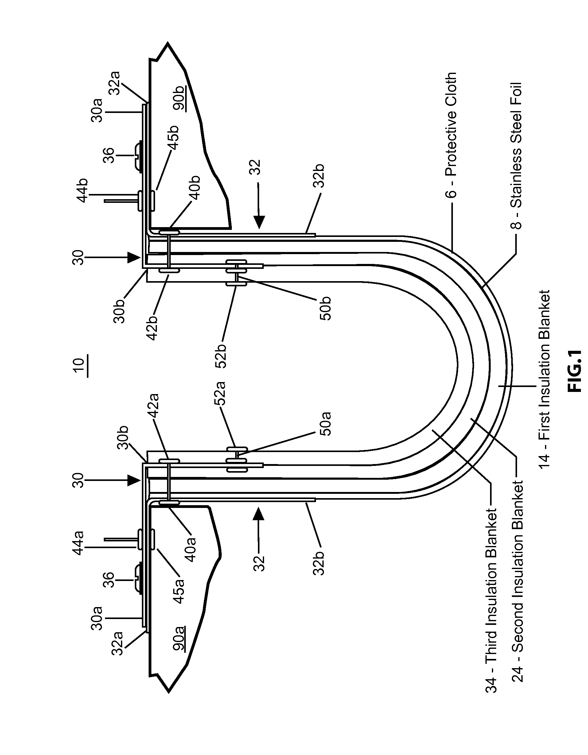
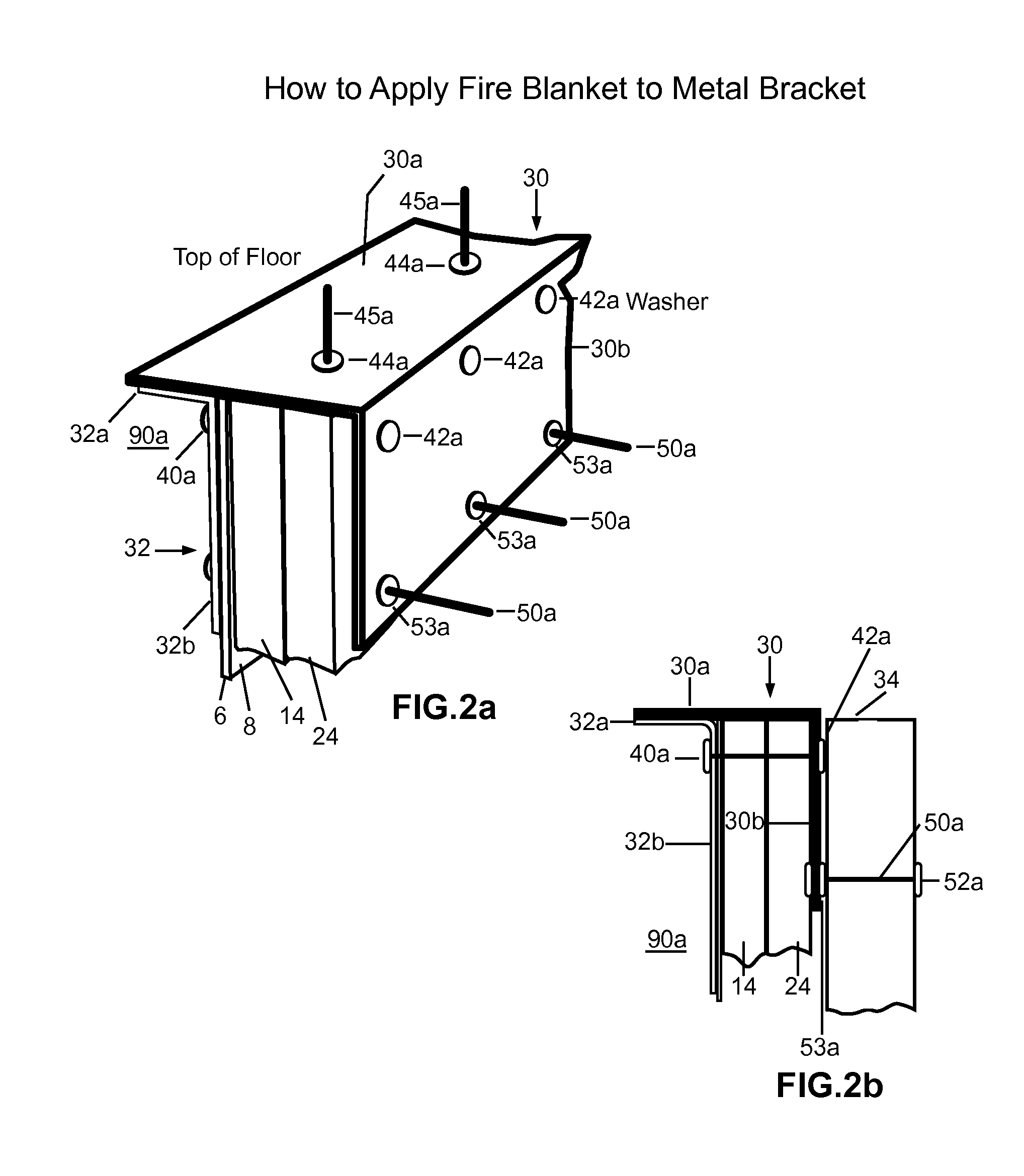
[0092]Referring now to the drawings that show views of exemplary versions of the barriers and their related installation tools contemplated by this invention. The drawings also illustrate how the above discussed disadvantages have been overcome. It should be noted that the disclosed invention is disposed to versions in various sizes, such as lengths, widths, depths, in addition to variation in shapes, contents, layers, materials, and attachment means. Therefore, the versions described herein are provided with the understanding that the present disclosure is intended as illustrative and is not intended to limit the invention to the versions described.

[0093]FIG. 1, a cross-sectional view, illustrates an example of the various layers a fire-barrier made according to the principles of the present invention might have. The construction of all fire-barriers made according to the principles of the present invention requires all layers comprise refractory material and that while one or more...


PUM


Abstract

Fire-barriers systems, including pre-assembled intersecting and straight-line fire-barriers having either all male-, all female-, or both types of coupling ends eliminate on-site cutting and construction of barriers required for intersection-spaces and provide easy, rapid, and safe one-step, drop-in installation and coupling. All male / female ended fire-barriers are constructed as single-piece units. All adjacent laid-flat layers are continuously connected having no gaps or folds. Straight-line and L-shaped barriers are certified according to the criteria mandated by both the ASTM E 1399-97 (Reapproved 2005), Standard Test Method for Cyclic Movement and Measuring the Minimum and Maximum Joint Widths of Architectural Joint Systems and the UL 2079 Fire Resistance of Building Joint Systems Test for air leakage (Revised and relocated as 1.14 Mar. 10, 2006).

Description

CROSS-REFERENCE TO RELATED APPLICATIONS[0001]This Continuation-In-Part Application for Patent claims the benefit of U.S. Continuation-In-Part patent application Ser. No. 12 / 855,639, filed Aug. 12, 2010 claiming benefit to U.S. Non-Provisional Patent Application No. 11 / 863,932 filed Sep. 28, 2007 claiming benefit to U.S. Provisional Patent Application No. 60 / 847,951 filed Sep. 28, 2006.STATEMENT REGARDING FEDERALLY SPONSORED RESEARCH OR DEVELOPMENT[0002]Not ApplicableREFERENCE TO SEQUENCE LISTING, A TABLE OR A COMPUTER PROGRAM LISTING COMPACT DISK APPENDIX[0003]Not ApplicableBACKGROUND OF THE INVENTION[0004]The present invention relates generally to fire-barriers for installing in expansion-joint-spaces and more particularly to pre-assembled fire-barriers constructed with male and female coupling-ends for one-step drop-in installation of the barriers into straight-line and intersecting expansion-spaces.[0005]The background information discussed below is presented to better illustrate...

Claims


Application Information

Patent Timeline
Patent Type & Authority Applications(United States)
IPC IPC(8): E04B1/94E04C2/02
CPCE04B1/948
Inventor SHAW, ALAN
Owner INPRO CORP
Learn More