Dust removal system for dust gas

a technology of dust gas and dust removal system, which is applied in the direction of liquid degasification, combustible gas purification/modification, separation processes, etc., can solve the problems of short working life of this kind of device, device out of action, and metal corrosion, so as to improve the atomizing effect of water, reduce the size of the water outlet, and improve the effect of water atomization

Active Publication Date: 2012-05-17
SHENZHEN SUNXING LIGHT ALLOYS MATERIALS CO LTD
View PDF11 Cites 4 Cited by
  • Summary
  • Abstract
  • Description
  • Claims
  • Application Information

AI Technical Summary

Benefits of technology

[0011]To resolve the present technical problems, this invention provides a dust removal system for dust gas. This system has a two-stage atomization—coordinating the atomizing balls and the water outlets, and using umbrella-shaped atomizer—to guarantee the atomizing effect, and at the same time to solve the present blocking and corrosion problems without increasing the clearing work and affecting the working life.
[0024]Compared with the prior art, the beneficial effect of this invention is: the two-stage atomization—coordinating the atomizing balls and the water outlets, and using an umbrella-shaped atomizer—guarantees the atomizing effect. When there are burrs accumulating in the water outlets, the size of the water outlets would decrease; regulate the fit clearances between the atomizing balls and the water outlets to remove completely the influence of the blockage on the atomizing effect. When there are burrs corroding the water outlets, the size of the water outlets would increase; regulate the fit clearances between the atomizing balls and the water outlets to remove completely the influence of the corrosion on the atomizing effect. According to the concentration of dust in the dust gas, correspondingly regulate the fit clearances between the atomizing balls and the water outlets to improve the atomizing effect for water. And properly regulate the flare angle of the umbrella surface of the umbrella-shaped atomizer to further improve the atomizing effect. So there are better atomizing effect and better contact effect between the water and the dust.

Problems solved by technology

The water mixture formed after the contact between this dust and NaOH solution has the following characteristics: first, high viscosity with high probability to adhere to metal surfaces; second, high probability to agglomerate with high speed of coagulation; third, corrosion to the metal in contact when the water mixture adheres to metal surfaces.
This kind of bag-type dust removal device can filter dust gas, however, dust with high viscosity and high probability to agglomerate would easily block the micro-holes of the bags so that gas could not go through the device normally and the device is out of action.
And the working life of this kind of device is very short; usually this device can work properly for only around 6 hours.
However, when water sprays through the dense small spouts, vapor-water mixture surrounds the dense small spouts, so burrs have a high probability to accumulate on the surfaces of the spouts in contact with the vapor-water mixture, so that spouts are blocked slowly to reduce the atomization effect and at the same time are corroded to reduce the working life of this device.
The necessity to clear burrs frequently in the process of using this device raises labor intensity and reduces the efficiency of removing dust.
So present dust removal equipments can not have stable, effective, and continually dust collection effect for the dust gas with compound dust.

Method used


Image

  • Dust removal system for dust gas
  • Dust removal system for dust gas
  • Dust removal system for dust gas

Examples


Embodiment Construction

[0031]Further description of this invention is made now through an embodiment of the invention and the accompanying drawings.

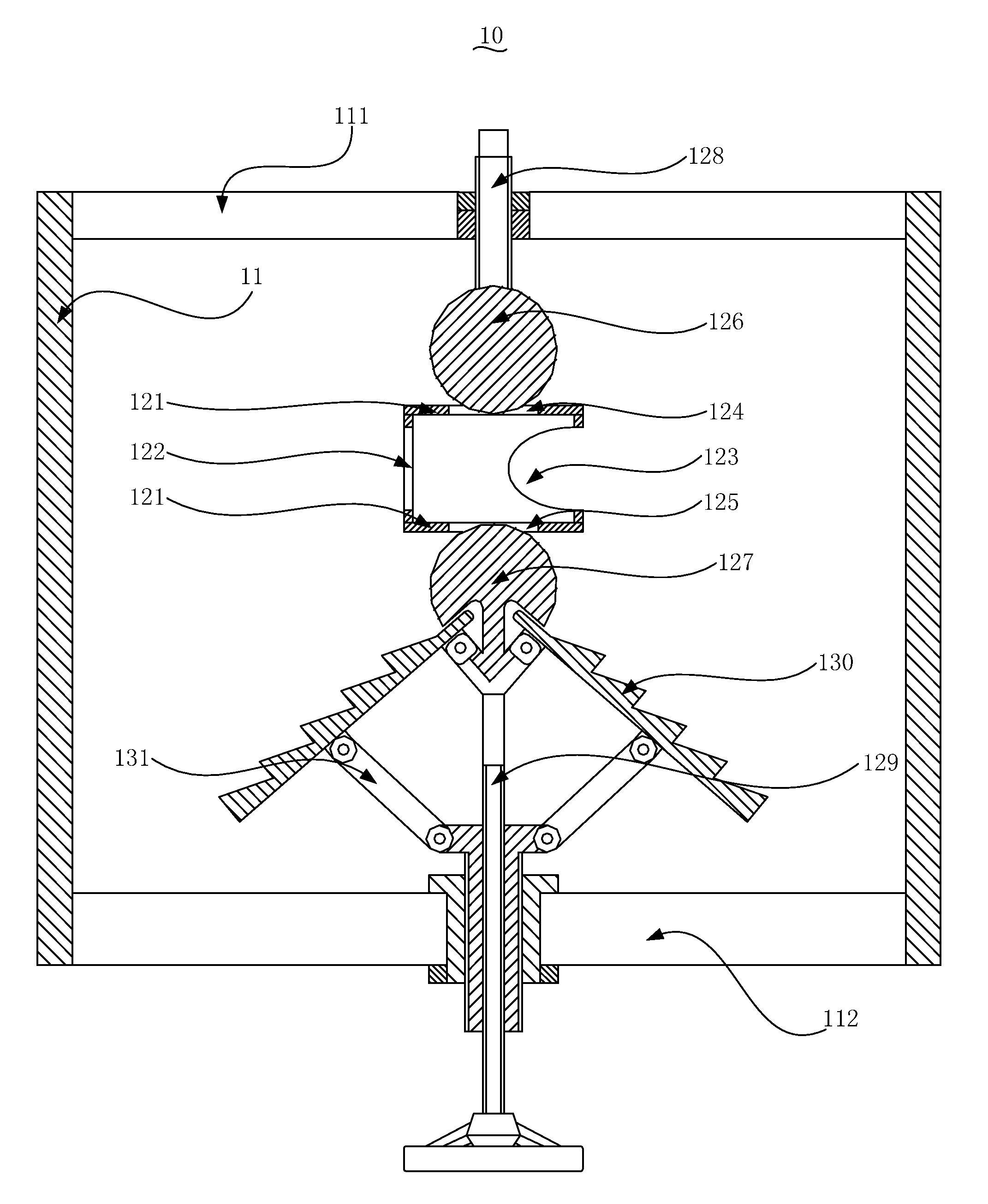
[0032]As shown in FIGS. 4, 5, and 6, a dust removal system for the dust gas includes an atomizer 10 which is used to mix the dust gas and water mist so that the water mist can absorb the dust in the dust gas to remove or reduce the concentration of dust in the dust gas, or is specially used to collect dust. The atomizer 10 includes an atomizing chamber 11 and an atomizing mechanism 12 set in the atomizing chamber 11. The atomizing chamber 11 includes an inlet for dust gas 111 and an outlet for gas after mixture 112; dust gas flows in atomizing chamber 11 from the inlet for the dust gas 111, contacts with water mist, and flows out from the outlet for the gas after mixture 112. The atomizing mechanism 12 is used to transform water flow to water mist; the dust gas and water mist in the atomizing chamber 11 has certain pressure. The atomizing mechanism 12 includes...


PUM

PropertyMeasurementUnit
Angleaaaaaaaaaa
Corrosion propertiesaaaaaaaaaa

Abstract

This invention is a dust removal system for dust gas which comprises at least an atomizer. The atomizer comprises an atomizing chamber and an atomizing mechanism; the atomizing chamber includes an inlet for the dust gas and an outlet for the gas after mixture; the atomizing mechanism comprises a water chamber, the first atomizing ball, the second atomizing ball, an umbrella-shaped atomizer, and a regulating mechanism; the water chamber includes the first and second water inlet and the first and second water outlet; the regulating mechanism adjusts the fit clearance between the first atomizing ball and the first water outlet, the fit clearance between the second atomizing ball and the second water outlet, and the flare angle of the umbrella surface of the umbrella-shaped atomizer. The beneficial effect is: the two-stage atomization—coordinating the atomizing balls and the water outlets, and using an umbrella-shaped atomizer—guarantees the atomizing effect. When there are burrs accumulating in the water outlets, regulate the fit clearances between the atomizing balls and the water outlets to remove completely the influence of the blockage on the atomizing effect. And when there are burrs corroding the water outlets, regulate the fit clearances between the atomizing balls and the water outlets to remove completely the influence of the corrosion on the atomizing effect.

Description

BACKGROUND OF THE INVENTION[0001]1. Field of the Invention[0002]This invention relates to the field of dust removal technology, more specifically to a dust removal system for dust gas.[0003]2. Description of the Related Arts[0004]In the present metal processing industry, lots of dust gas is produced in the process of machining of metals. The dust in the dust gas comprises mostly different compounds.[0005]For example, in the productive process of aluminum-titanium-boron alloy, the produced dust includes the following components: BF3, AlF3, Al2O3, KAlF4, K2TiF6, K8F4 and the dust mixes with air to form dust gas. The water mixture formed after the contact between this dust and NaOH solution has the following characteristics: first, high viscosity with high probability to adhere to metal surfaces; second, high probability to agglomerate with high speed of coagulation; third, corrosion to the metal in contact when the water mixture adheres to metal surfaces.[0006]Presently, there are mai...

Claims


Application Information

Patent Timeline
IPC IPC(8): B01D47/06
CPCB01D47/06B01D2247/04B01D2247/08B05B1/308B01D2247/14B05B1/265B01D2247/101
Inventor CHEN, XUEMINYE, QINGDONGZHOU, SIHAI
Owner SHENZHEN SUNXING LIGHT ALLOYS MATERIALS CO LTD
Why Eureka
Try Eureka