Apparatus for cleaning paint rollers and brushes

Inactive Publication Date: 2012-05-17
PICCIONI BRIAN JOSEPH
View PDF11 Cites 16 Cited by
  • Summary
  • Abstract
  • Description
  • Claims
  • Application Information

AI Technical Summary

Benefits of technology

[0018]Preferably, the shaft and holder of the drill attachment are held in axial alignment during rotation by the opening in the cap, or a bushing provided in the centre of the cap. The user may steady the cylinder by holding it if the need should arise. During typical use, the user would remove the drill from the shaft prior to operation, and when solvent or water is added to, or drained from the cylinder, which is accomplished by unscrewing the cap and pouring the water or solvent in to (or out of) the cylinder. It is not necessary to completely remove the cap in either case, therefore the soiled roller can be left in the cylinder, or, when emptying the solvent or water, the top cap retains the roller, shaft, and holder assembly and prevents the user's hand from being splashed with solvent, water, or paint.
[0019]The simple design allows for the container and cap to be molded from plastic or resin

Problems solved by technology

A larger diameter results in excess use of solvent or water.
In terms of diameter, it is important to have some distance from the roller cov

Method used


Image

  • Apparatus for cleaning paint rollers and brushes
  • Apparatus for cleaning paint rollers and brushes
  • Apparatus for cleaning paint rollers and brushes

Examples


Example

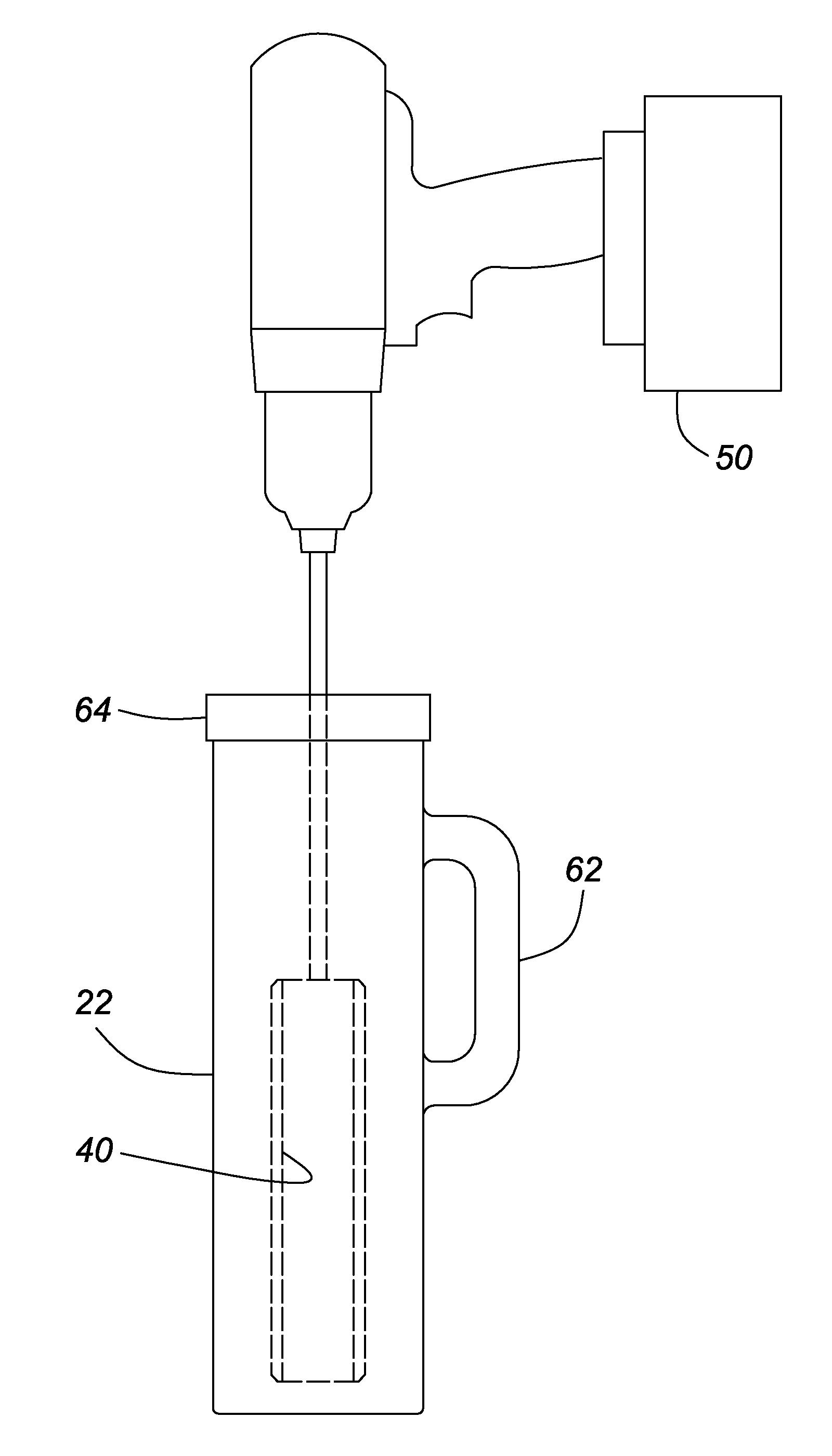
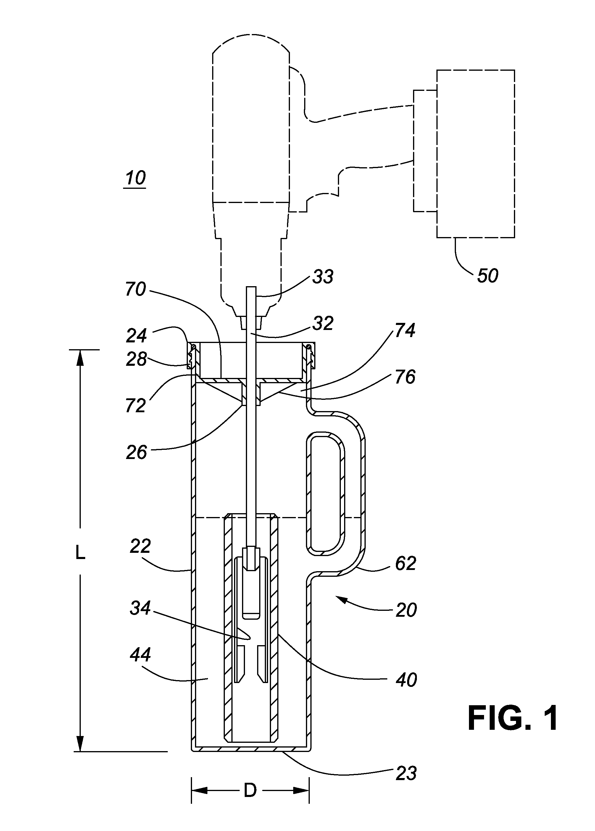
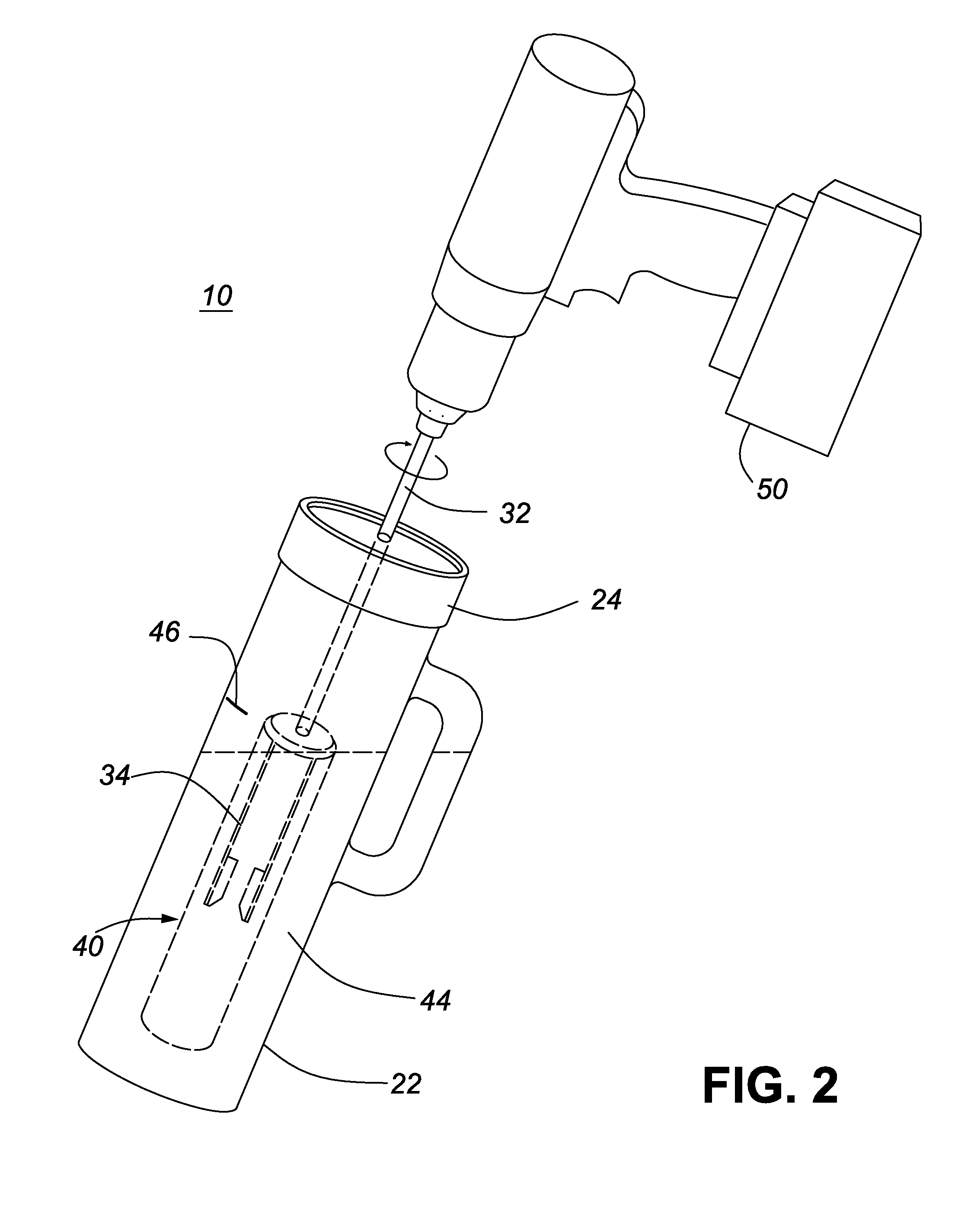
[0037]An apparatus for cleaning paint rollers and paint brushes according to a first embodiment of the present invention is shown schematically in FIGS. 1 to 5. The apparatus 10 comprises an attachment 30 for a power tool, such as an electric drill 50. The attachment 30 comprises a shaft 32, e.g. a ¼ inch diameter steel rod, having at one end, a holder 34 in the form of a combined paint roller holder and paint brush clamp for holding a roller cover 40 or a brush 42 during cleaning. The other end of the shaft 33 is designed to be coupled to the power tool 50, i.e. clamped in the chuck of the drill, to enable the attachment 30 to be spun at high-speed during operation. The apparatus also comprises a container assembly 20, in the form of a tubular, e.g. cylindrical, container 22 and cap / cover 24. The container has a closed end at the base 23, and an open end 25 at the top for receiving the holder of the drill attachment with the paint roller cover or brush mounted on the holder. The co...

Example

[0047]An apparatus according to a second embodiment is shown in FIG. 6. All parts are similar to those shown in FIG. 1, and similarly numbered, except that the container has a conical base 38, and optionally includes a valve 48, which in this example, is near the base of the container 22. Alternatively or additionally, (not shown) a valve may be provided near the top of the container, or in the cap to allow the container to be drained and / or filled without removing the cap. The convex conical base 38 further reduces the internal volume, assists in maintaining alignment of the roller cover during high-speed rotation, and may assist in collecting sediment or particulates. As mentioned above, an optional metal bushing 27 may be provided within the opening 26 of the cap 24, to provide a durable bearing surface for axial alignment and free rotation of the shaft 32. If required, a sealing element 29, such as an O-ring, is provided between the rim 25 at the open end of the container and th...


PUM


Abstract

An apparatus is provided for cleaning paint rollers and/or brushes. It comprises a roller cover/brush holder that may be coupled to a drill or other power tool, and a container and cap assembly. Advantageously, the container accommodates the holder and a roller cover or paintbrush with a minimal effective volume of cleanser. The cap closes and substantially seals the container to contain spray or spillage during high-speed rotation of the holder within the container. In use, the container is filled with cleanser, such as soapy water, and the roller is spun for several minutes. The container is drained, then refilled with rinse water and the process is repeated as needed. The roller or brush may be spun dry after cleaning, or between wash and rinse cycles. The apparatus provides effective cleaning with a reduced volume of water or cleanser and requires minimal clean-up.

Description

CROSS-REFERENCE TO RELATED APPLICATION[0001]This application claims priority from U.S. Provisional Patent Application No. 61 / 414,505, filed 17 Nov. 2010, entitled “Apparatus for Cleaning Paint Rollers and Brushes”, which is incorporated herein by reference, in its entirety.TECHNICAL FIELD[0002]This invention relates to apparatus for cleaning paint applicators, such as paint rollers and paint brushes, and more particularly, to apparatus for cleaning paint rollers that may be coupled to an electric drill to spin the roller during cleaning.BACKGROUND[0003]Numerous prior art products are known for cleaning paint brushes and paint rollers. Although oil based or alkyd paints require volatile and often flammable solvents for clean-up, water-based paints are now widely available that allow for water clean-up using soap and water. Nevertheless, cleaning paint rollers thoroughly usually requires copious amounts of water, resulting in gallons of paint-contaminated water being washed down the d...

Claims


Application Information

Patent Timeline
IPC IPC(8): B08B3/04B08B7/00
CPCB44D3/006A46B17/06
Inventor PICCIONI, BRIAN JOSEPH
Owner PICCIONI BRIAN JOSEPH
Why Eureka
Try Eureka