Retractable Fall Arrest WIth Component Assembly and Cantilevered Main Shaft

a technology of cantilever main shaft and component assembly, which is applied in the direction of safety belts, sports equipment, cleaning equipment, etc., can solve the problems of mechanical difficulty, periodically inspected, and high maintenance cost, and achieves the effect of reducing maintenance costs and time-consuming

Inactive Publication Date: 2012-05-17
RELIANCE INDUSTRIES LIMITED
View PDF29 Cites 56 Cited by
  • Summary
  • Abstract
  • Description
  • Claims
  • Application Information

AI Technical Summary

Benefits of technology

[0007]Briefly, a retractable fall arrestor is disclosed which is substantially corrosion resistant and which is made from component assemblies, thereby allowing workers in the field to replace any needed component of the retractable. Further, t...

Problems solved by technology

One of the difficulties of using mechanical retractable shock absorbing lifelines is that they must be periodically inspected for damage and be retested to confirm that they are operating correctly.
The reason these units must be returned to the manufacturer is because they are mechanically difficult to service due to the precision setting required on the clutch assembly and the difficulty of unloading and removing the power retraction springs, whic...

Method used


Image

  • Retractable Fall Arrest WIth Component Assembly and Cantilevered Main Shaft
  • Retractable Fall Arrest WIth Component Assembly and Cantilevered Main Shaft
  • Retractable Fall Arrest WIth Component Assembly and Cantilevered Main Shaft

Examples


Embodiment Construction

[0029]The following detailed description illustrates the invention by way of example and not by way of limitation. This description will clearly enable one skilled in the art to make and use the invention, and describes several embodiments, adaptations, variations, alternatives and uses of the invention, including what I presently believe is the best mode of carrying out the invention. Additionally, it is to be understood that the invention is not limited in its application to the details of construction and the arrangements of components set forth in the following description or illustrated in the drawings. The invention is capable of other embodiments and of being practiced or being carried out in various ways. Also, it is to be understood that the phraseology and terminology used herein is for the purpose of description and should not be regarded as limiting.

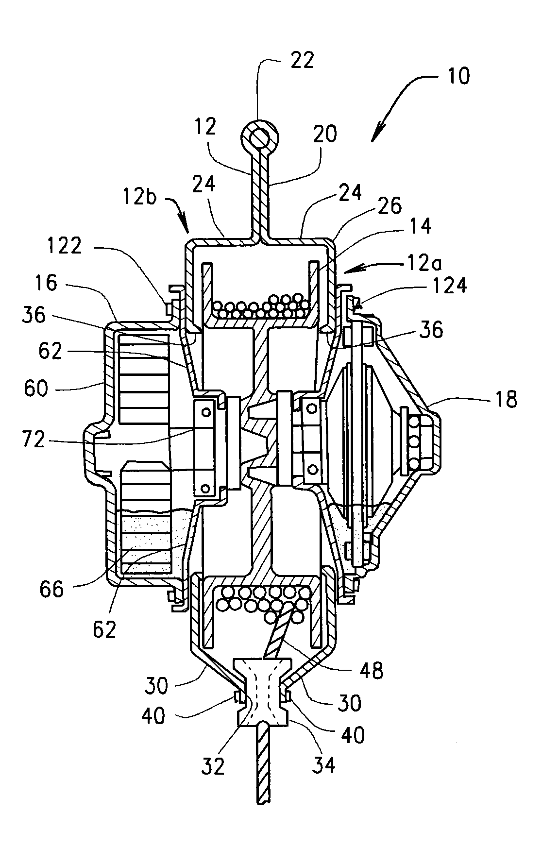
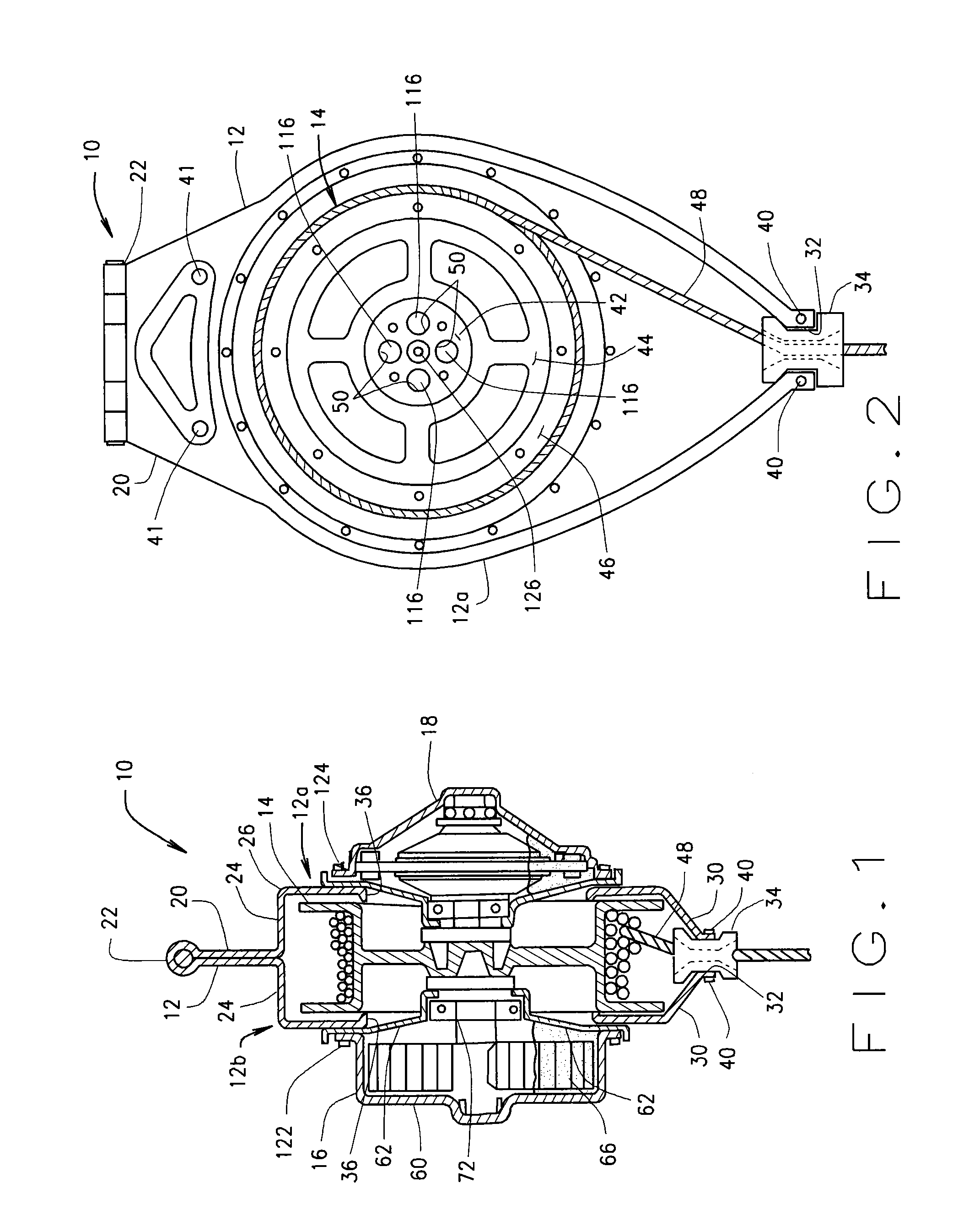
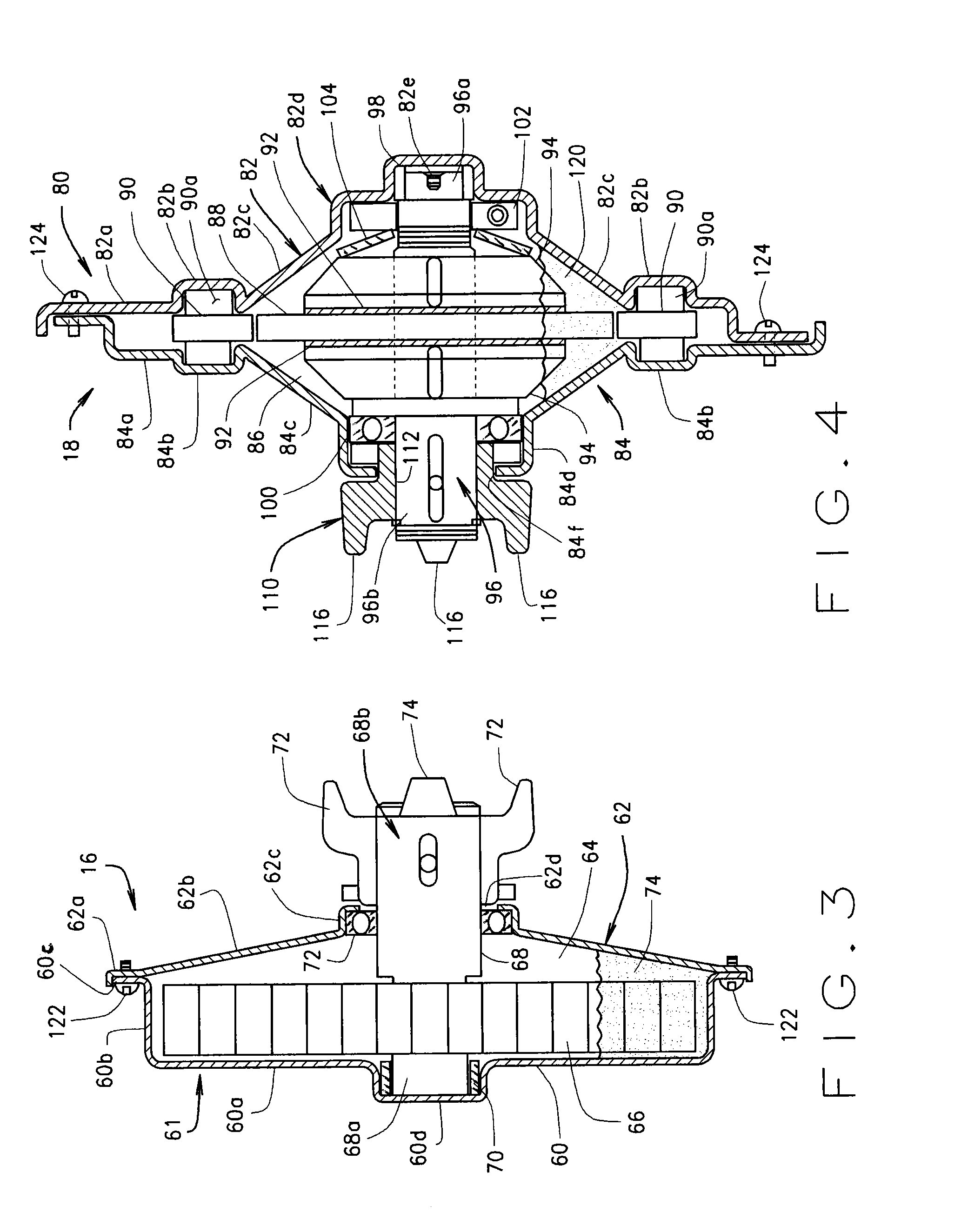
[0030]Referring initially to FIG. 1, a retractable fall arrest unit 10 is comprised of four components: a housing 12, a dru...


PUM


Abstract

A retractable fall arrest device comprises a unit housing, a spring sub-assembly, a brake/clutch sub-assembly, and a drum assembly. The spring and brake/clutch sub-assemblies each include shaft portions which extend into the housing and are removably connected together or to the drum assembly, and support the drum assembly in the housing. The spring and brake/clutch assembly are themselves removably connected to the unit housing. Finally, the unit housing comprises two wall members (i.e., clam shells) which are removably connected together. This fall arrest device allows for replacement of any of the four constituent components of the device in the field, thus reducing the down time between repairs or recertification of a particular fall arrest device.

Description

CROSS-REFERENCE TO RELATED APPLICATIONS[0001]This application claims priority to U.S. Prov. App. No. 61 / 458,107 filed Nov. 17, 2010, which is incorporated herein by reference.STATEMENT REGARDING FEDERALLY SPONSORED RESEARCH OR DEVELOPMENT[0002]Not Applicable.BACKGROUND OF THE INVENTION[0003]This application relates to fall arrest units, and, in particular to a fall arrest unit comprised of easily assemblable components.[0004]Retractable fall arrests or lifelines have been used for many years and range in size from small (6 ft) units to large (175 ft) units. The purpose of a retractable lifeline or fall arrest unit is to allow workers, who must work on the leading edge of elevated surfaces (or other areas were falls are of concern) to have a means to attach to an overhead anchorage that will arrest their motion in case of an accidental fall. These retractables are usually equipped with a 3 / 16″ wire rope cable or a 1″ webbing lanyard of at least 4700 lb of anchorage strength. The retr...

Claims


Application Information

Patent Timeline
IPC IPC(8): A62B1/10A62B1/00
CPCA62B1/10
Inventor OLSON, WAYNE L.CHOATE, GARY E.
Owner RELIANCE INDUSTRIES LIMITED
Why Eureka
Try Eureka