
Method for controlling a motor

Active Publication Date: 2012-05-17
KSB AG
View PDF14 Cites 11 Cited by
  • Summary
  • Abstract
  • Description
  • Claims
  • Application Information

AI Technical Summary

Benefits of technology

[0017]The object of the present invention is to at least partially overcome the above drawbacks, by providing a method for controlling a motor that can increase the efficiency thereof even at low torque settings.
[0018]Another object is to provide a method for controlling a motor that can increase efficiency at low running speeds even in sensorless motors, i.e. motors with no sensor for detecting the rotation speed and the position of the rotor during operation.
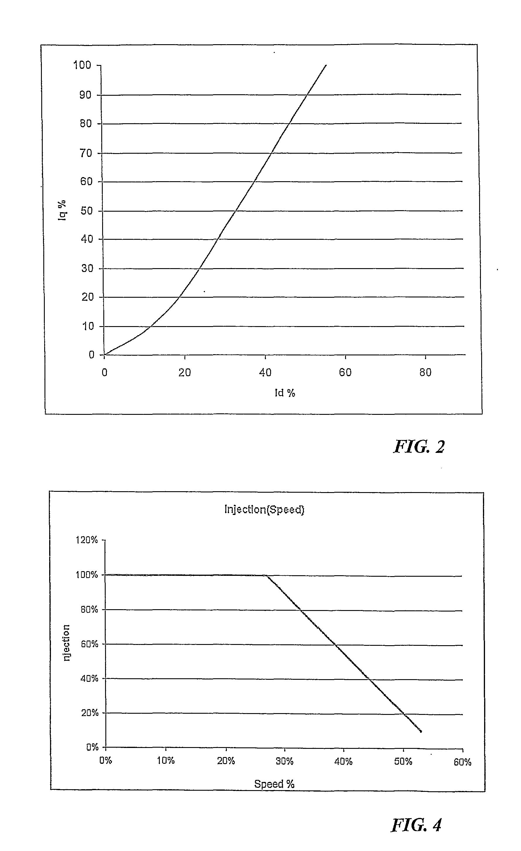
[0026]In other words, the direct current Id is not constant, but changes with the quadrature current Iq. This allows optimization of the power current supplied to the motor according to the torque it is designed to develop. As a result, the efficiency of the motor so controlled is optimized.
[0028]Therefore, the variation of the direct current Id as a function of the quadrature current Iq is related to the maximum obtainable torque constant, i.e. the optimization of the power current supplied to the motor is related to the maximum torque constant. This provides maximized motor efficiency.
[0033]The motor magnetization flux depends on the direct current Id, which prevents demagnetization of the motor under minimal loads.
[0034]Likewise, the method may include an additional step of conditioning the direct current Id, where the latter is limited by a predetermined maximum limit value. This prevents saturation of the motor with an excessive magnetization flux.

Problems solved by technology

Nevertheless, this affects efficiency, because the motor is always powered at the maximum capacity, even in case of minimal torque requirement, i.e. when the motor can run at low speed.
In other words, while this arrangement keeps motor efficiency unaltered at high running speeds, efficiency is decreased, possibly to a considerable extent, at low running speeds.
While this improves motor efficiency by decreasing the current supplied thereto at low running speeds, it still involves the drawback that such control is an indirect, non optimal manner to act upon direct current.
Such solution is apparently not optimal, especially in the presence of mixed loads.
In other words, even when prior art motors are controlled by a field orientation vectorial technique to assimilate them to a DC motor, they still have efficiency losses at low running speeds, although control involves a change of both quadrature and direct currents.
In this type of motors, this problem is even more serious.
While the rotation speed and position of the rotor may be detected using the back electromotive force at high running speeds, the inherent impedance of the motor prevents the use of this method at low running speeds.
Nevertheless, such added voltage at low running speeds induces additional work in the motor, which results in an efficiency loss.

Method used


Image

  • Method for controlling a motor
  • Method for controlling a motor
  • Method for controlling a motor

Examples


Embodiment Construction

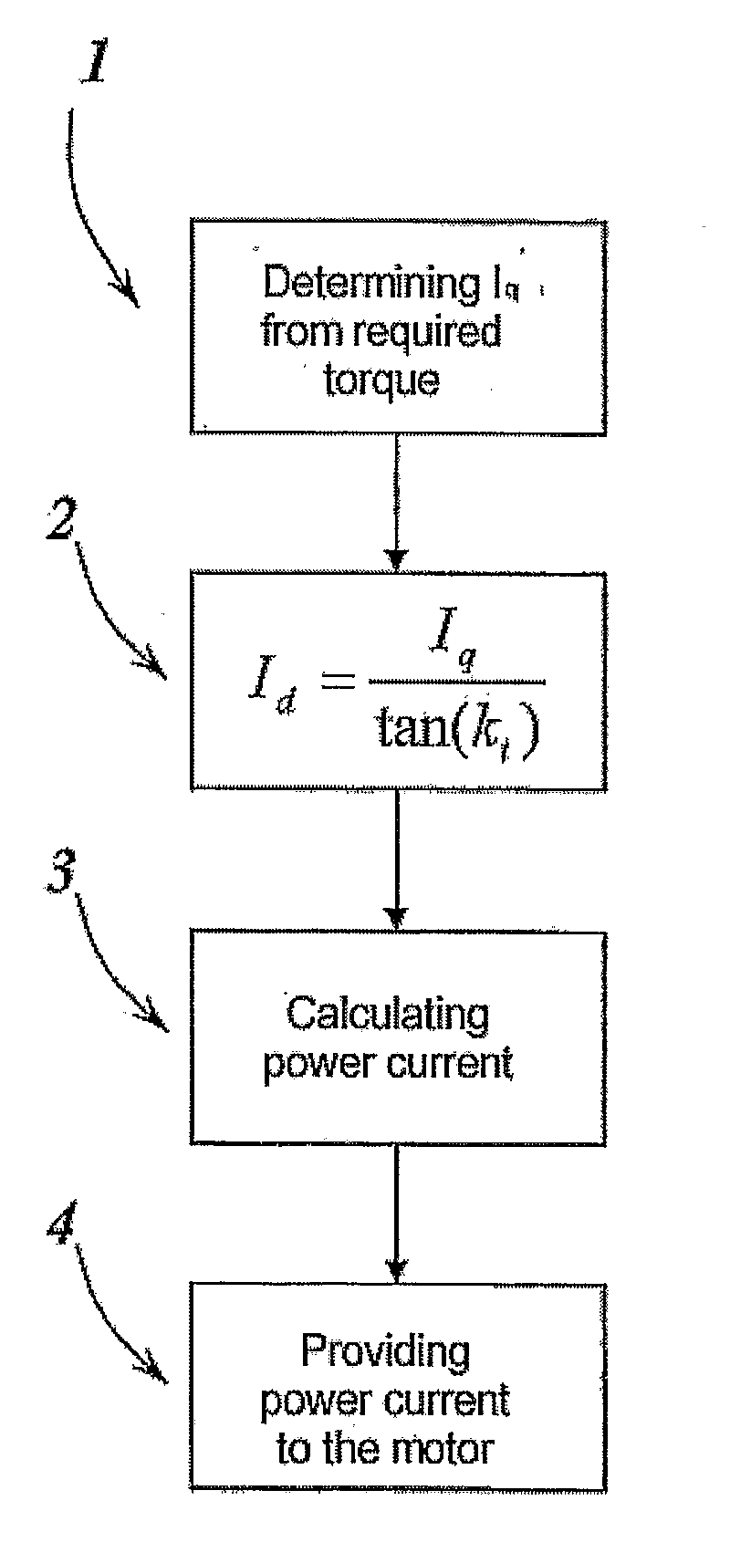
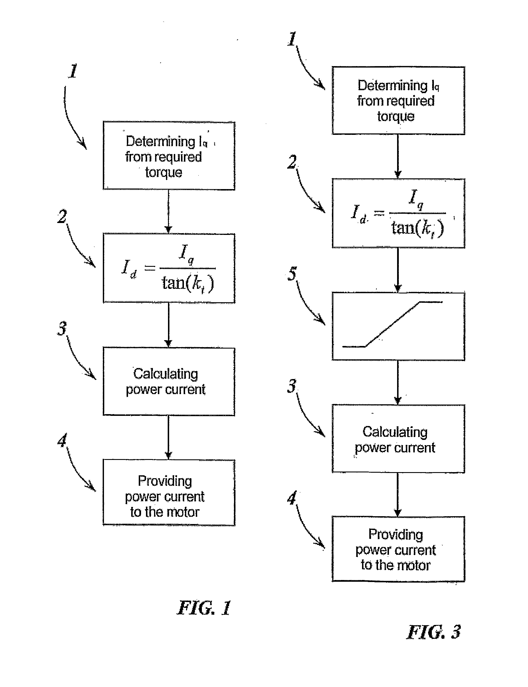
[0040]Referring to FIG. 1, there is described a method for controlling a motor by a vectorial technique and an inverter.

[0041]As mentioned above, the use of a vectorial technique allows control of a general motor as if it were a DC motor, with all advantages deriving therefrom. Therefore, the invention described herein will be related to a general motor, even when it is specifically applied in the control of synchronous reluctance motors.

[0042]The method described herein comprises a first step, designated by numeral 1, where the value of the quadrature current Iq is determined. As is known and mentioned hereinabove, this current is responsible for the mechanical torque delivered by the motor. Once the load and the torque to be delivered by the motor are known, the quadrature current Iq is determined.

[0043]In a later step, designated by numeral 2, the direct current Id to be supplied to the motor is determined by the equation:

Id=Iqtan(kt)

wherein kt is the phase of the current, which ...


PUM


Abstract

A method for controlling a motor by an inverter and by a vectorial technique, comprising the following steps: determining the value of a quadrature current Iq necessary for said motor to generate the desired torque; calculating the value of a direct current to be supplied to the motor by an equation as a function of the phase of the current vector on which the torque constant of the motor depends; calculating the power current of said motor from the direct current and the quadrature current; supplying the power current to the motor through the inverter.

Description

FIELD OF THE INVENTION[0001]The present invention generally finds application in the field of electric drives for motors.[0002]Particularly, the present invention relates to motor control by electric drives, generally equipped with inverters.BACKGROUND ART[0003]In modern technology, motors are among the most commonly used elements in various applications. Many types of different motors have been developed and used, according to particular types of applications. For example, motors may be grouped into synchronous and asynchronous motors or DC or AC motors.[0004]In any case, the need is increasingly felt to improve the efficiency of such motors. In view of the above, there are many applications in which motors might deliver a variable torque at different working time. For this reason, in order to improve efficiency, it might be useful to change the motor speed to avoid energy wastes when the motor might work in a slow running state.[0005]Thus, electric drives with inverters are used, ...

Claims


Application Information

Patent Timeline
IPC IPC(8): H02P21/00
CPCH02P21/146H02P21/0035H02P21/18H02P21/22Y02P80/10
Inventor BERTOTTO, EZIODI SANTO, FEDERICOMARODIN, ENRICO
Owner KSB AG
Learn More