Control circuit for switching power supply

a control circuit and power supply technology, applied in the field of light emitting devices, can solve the problems of affecting the operation of the electronic device, and affecting the user's comfort, so as to reduce the duty ratio of the pulse signal, reduce the length of the on period of the switching element, and suppress the acoustic noise

Active Publication Date: 2012-05-17
ROHM CO LTD
View PDF3 Cites 35 Cited by
  • Summary
  • Abstract
  • Description
  • Claims
  • Application Information

AI Technical Summary

Benefits of technology

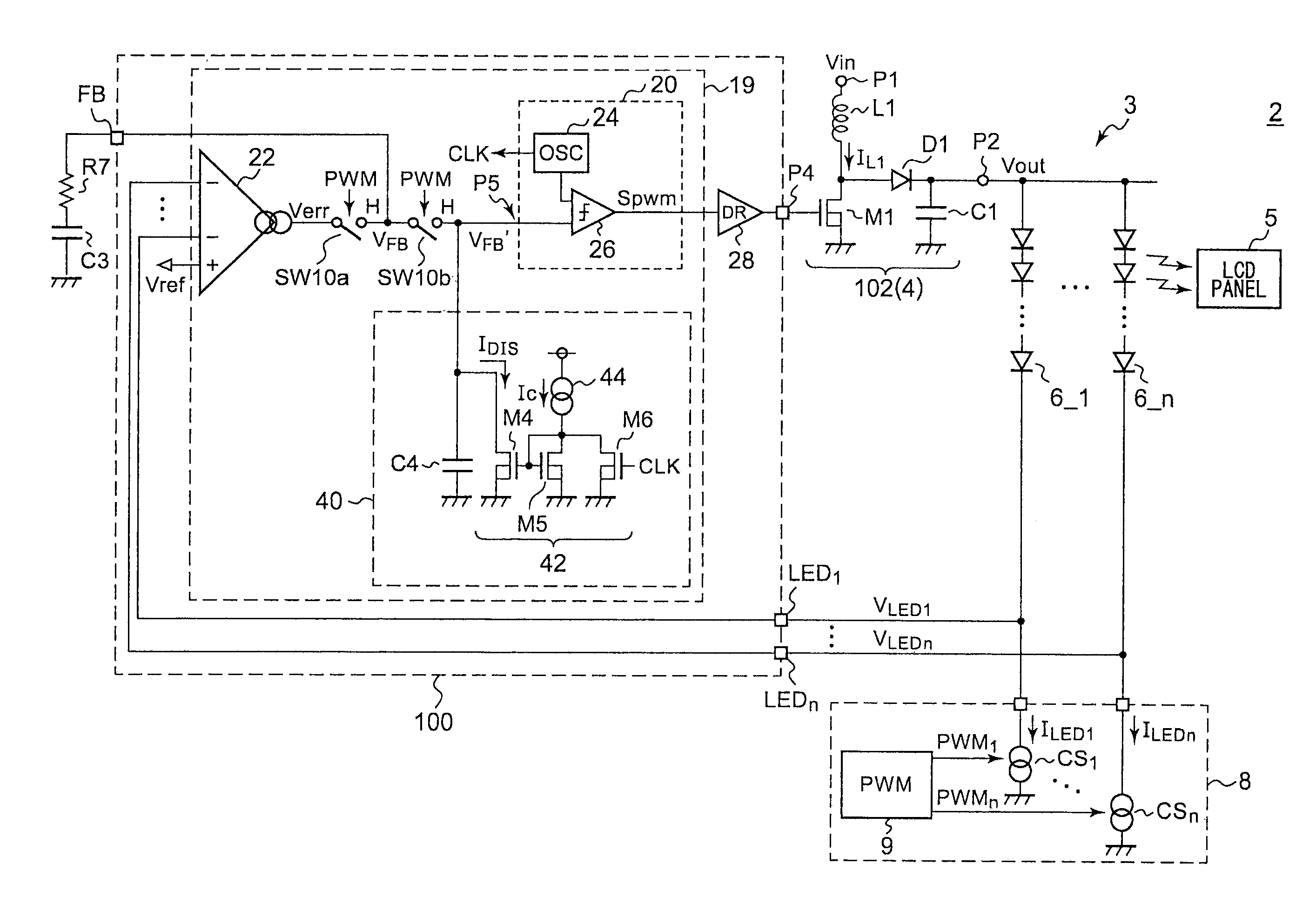
[0013]The present invention has been made in order to solve such a problem. Accordingly, it is an exemplary purpose of an embodiment of the present invention to provide a control circuit which is capable of suppressing acoustic noise that occurs in the coil in the PWM driving operation.
[0014]An embodiment of the present invention relates to a control circuit for a switching power supply configured to supply a driving voltage to one terminal of a light emitting element to be intermittently driven. The control circuit comprises: a pulse modulator configured to generate a pulse signal having a duty ratio adjusted such that a detection voltage that corresponds to the output voltage of the ...

Problems solved by technology

This becomes a cause of acoustic noise (which is also referred to as a “rumbling sound”) that occurs in...

Method used


Image

  • Control circuit for switching power supply
  • Control circuit for switching power supply
  • Control circuit for switching power supply

Examples


Embodiment Construction

[0032]The invention will now be described based on preferred embodiments which do not intend to limit the scope of the present invention but exemplify the invention. All of the features and the combinations thereof described in the embodiment are not necessarily essential to the invention.

[0033]In the present specification, the state represented by the phrase “the member A is connected to the member B” includes a state in which the member A is indirectly connected to the member B via another member that does not substantially affect the electric connection therebetween, or that does not damage the functions or effects of the connection therebetween, in addition to a state in which the member A is physically and directly connected to the member B.

[0034]Similarly, the state represented by the phrase “the member C is provided between the member A and the member B” includes a state in which the member A is indirectly connected to the member C, or the member B is indirectly connected to ...


PUM


Abstract

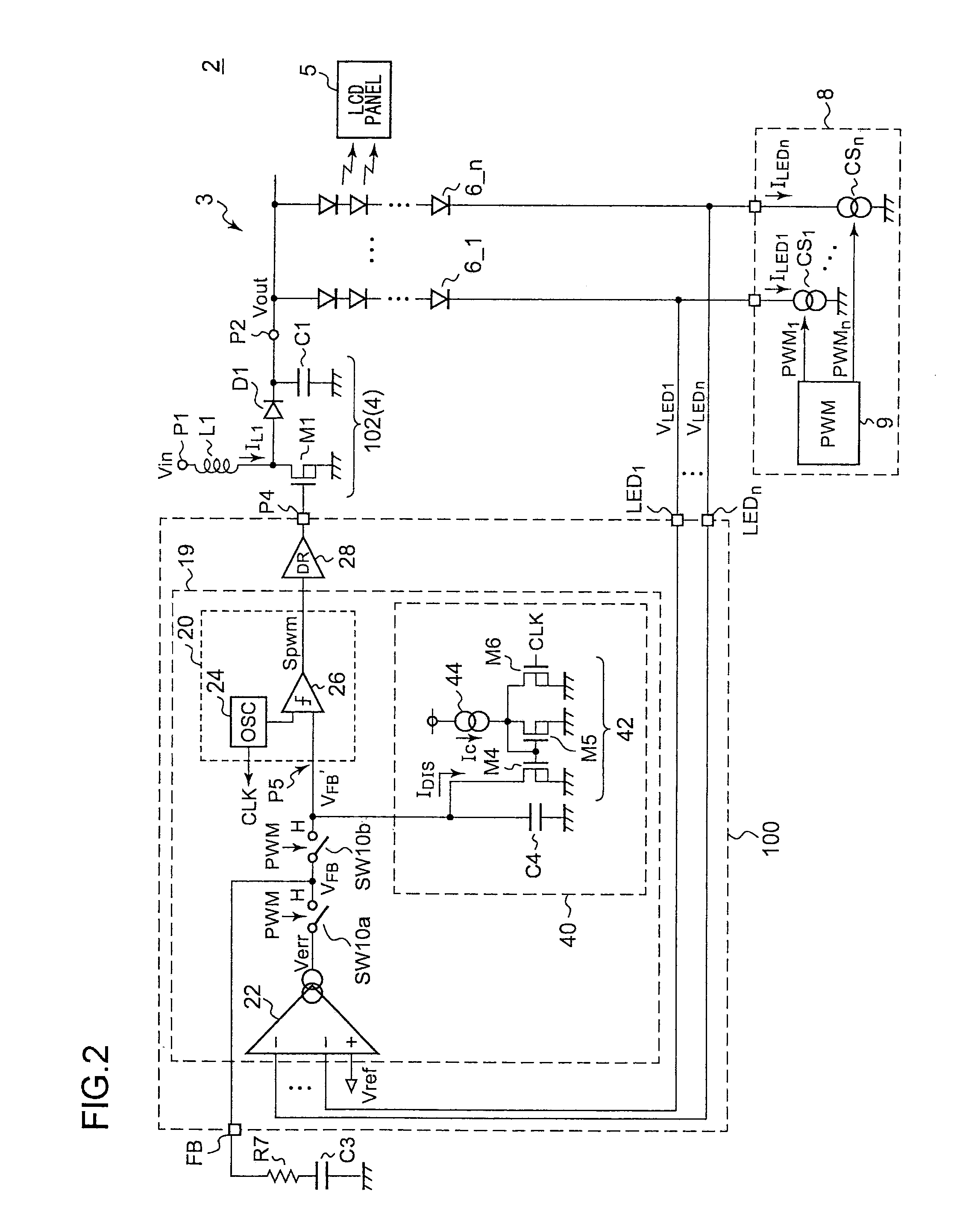
A control IC controls a switching power supply configured to supply a driving voltage Vout to one terminal of an LED string to be intermittently driven. In the on period of the LED string, a pulse modulator generates a pulse signal having a duty ratio adjusted such that a detection voltage VLED that corresponds to the output voltage Vout of the switching power supply matches a predetermined reference voltage Vref. A driver drives a switching transistor included in the switching power supply according to the pulse signal. After transition from the on period to the off period, the pulse modulator reduces the duty ratio of the pulse signal over time.

Description

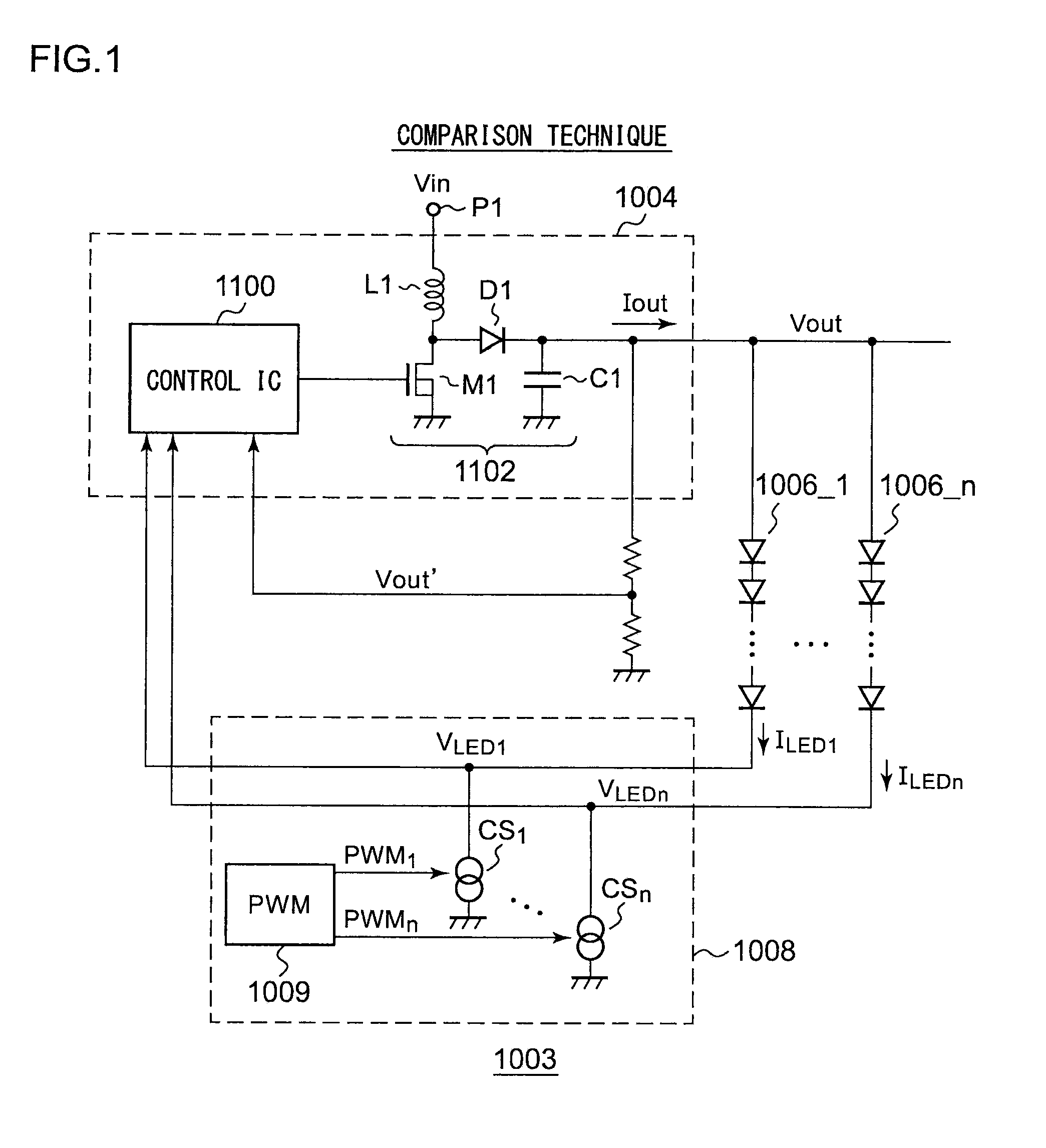
BACKGROUND OF THE INVENTION[0001]1. Field of the Invention[0002]The present invention relates to a light emitting apparatus.[0003]2. Description of the Related Art[0004]In recent years, as a backlight of a liquid crystal panel or as an illumination device, a light emitting apparatus is employed, which is configured using a light emitting element such as an LED (light emitting diode) or the like. FIG. 1 is a circuit diagram which shows an example configuration of a light emitting apparatus according to a comparison technique. A light emitting apparatus 1003 includes multiple LED strings 1006_1 through 1006—n, a switching power supply 1004, and a current driving circuit 1008.[0005]Each LED string 1006 includes multiple LEDs connected in series. The switching power supply 1004 boosts an input voltage Vin, and supplies a driving voltage Vout to one terminal of each of the LED strings 1006_1 through 1006—n. [0006]The current driving circuit 1008 includes current sources CS1 through CSn w...

Claims


Application Information

Patent Timeline
IPC IPC(8): G02F1/13357H05B37/02
CPCH02M3/156H02M2001/009H05B33/0815G09G2330/028G09G3/3406Y02B20/346G09G2320/064H05B33/0827H05B45/3725H05B45/46H02M1/009Y02B20/30
Inventor UCHIMOTO, DAISUKEKIKUCHI, HIROKI
Owner ROHM CO LTD
Why Eureka
Try Eureka