Method for Generating Bone Mask

a bone mask and computed tomography technology, applied in the field of computed tomography (ct) scans, can solve the problems of affecting the accuracy of bone masks, and affecting the diagnosis accuracy of computed tomography angiography, so as to achieve better and clearer image quality, reduce computational artifacts, and improve the effect of defining the range of bone masks

Active Publication Date: 2012-05-17
NAT CENT UNIV
View PDF10 Cites 26 Cited by
  • Summary
  • Abstract
  • Description
  • Claims
  • Application Information

AI Technical Summary

Benefits of technology

[0009]In view of the problems of prior techniques as aforementioned, one objective of the present invention is to provide a method for generating a bone mask. The bone mask is then used for eliminating the corresponding bone structures in the postcontrast helical CT images in order to further resolve the problem of viewing obstruction caused by bone structures for blood vessels and other organs and tissues, and get bone-free images.
[0016]As stated above, the method for generating a bone mask as proposed in this invention possesses one or several of the following advantages:
[0018](2) Due to the fact that axial CT possesses an advantage over helical CT in producing less computational artifacts. Therefore, the bone-free images acquired by utilizing the bone mask that generated by the present invention is able to have better and clearer image quality. In a preferred embodiment, in the thresholding step, the periphery of the bone mask is color-marked. This helps to define the range of the bone mask more accurately. When the bone mask generated by the present invention is used to eliminate the corresponding bone structures from the data of postcontrast helical CT scan, a problem in earlier techniques that the vessels in an angiography image are smaller than the real vessels can be overcome, so that a more accurate angiography image is presented.
[0019](3) The present invention can further reduce the total radiation dose that a patient is exposed to, and is thereby more suitable than the prior art to use on subjects who are radiation-sensitive and prone to side effects of radiation (e.g. children).

Problems solved by technology

Although three-dimensional visualization and computer-aided analytic techniques such as maximum intensity projection (MIP), volume rendering and arterial lumen analysis are readily available, fully automated image processing for CTA data in the brain has been hampered by the presence of surrounding bony structures, particularly in the region of the skull base.
When the value of Hounsfield unit (HU) for the contrast-enhanced blood vessels following the injection of contrast medium falls within the HU range of the bone and the calcification, diagnosis by computed tomography angiography becomes more difficult.
Conversely, even though bone editing and vessel segmentation methods do not require any additional, precontrast CT scan, these methods involves drawbacks of having a certain degree of computational complexity and having significant differences in results edited by different operators.

Method used


Image

  • Method for Generating Bone Mask
  • Method for Generating Bone Mask
  • Method for Generating Bone Mask

Examples


first embodiment

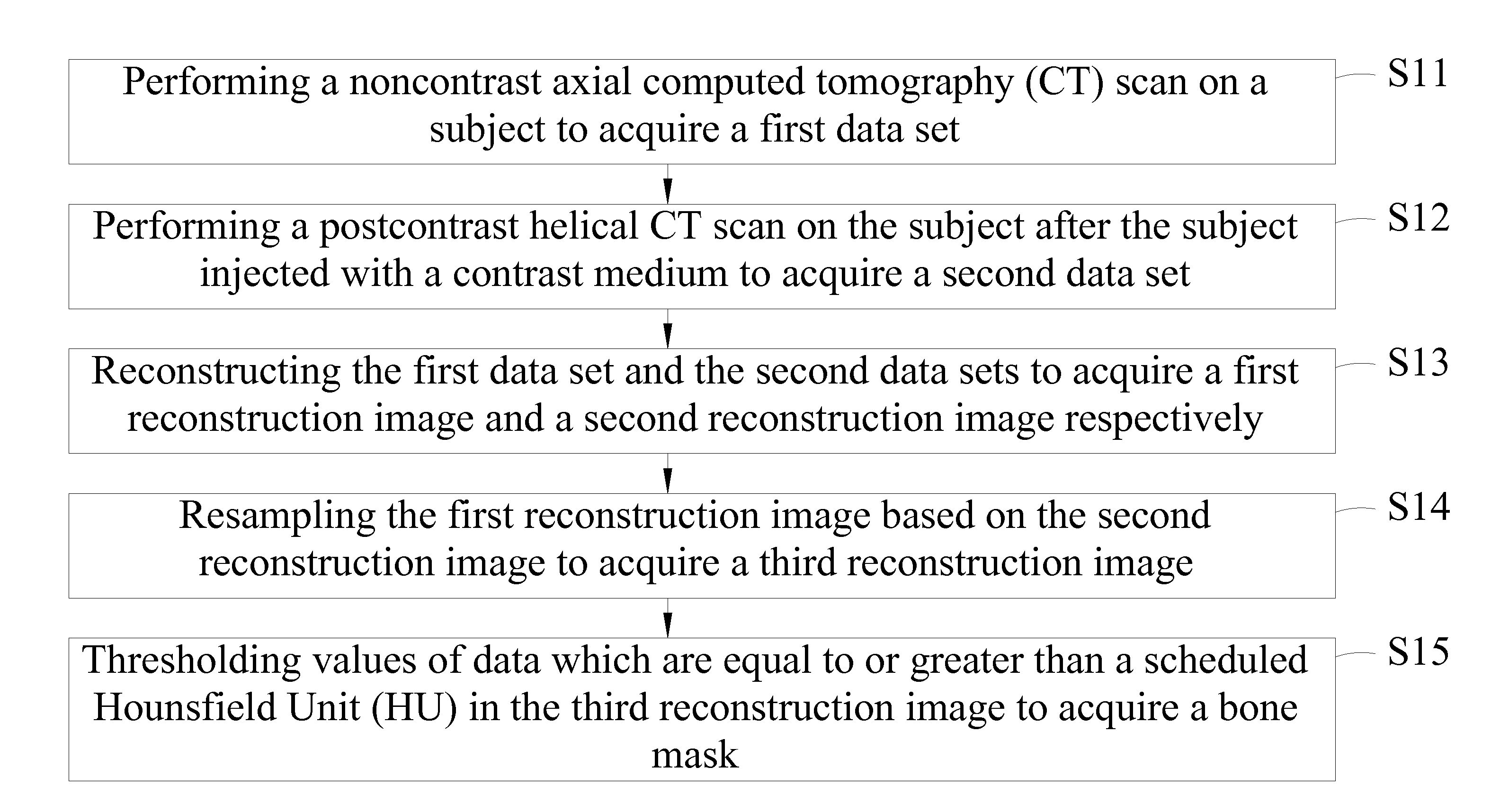
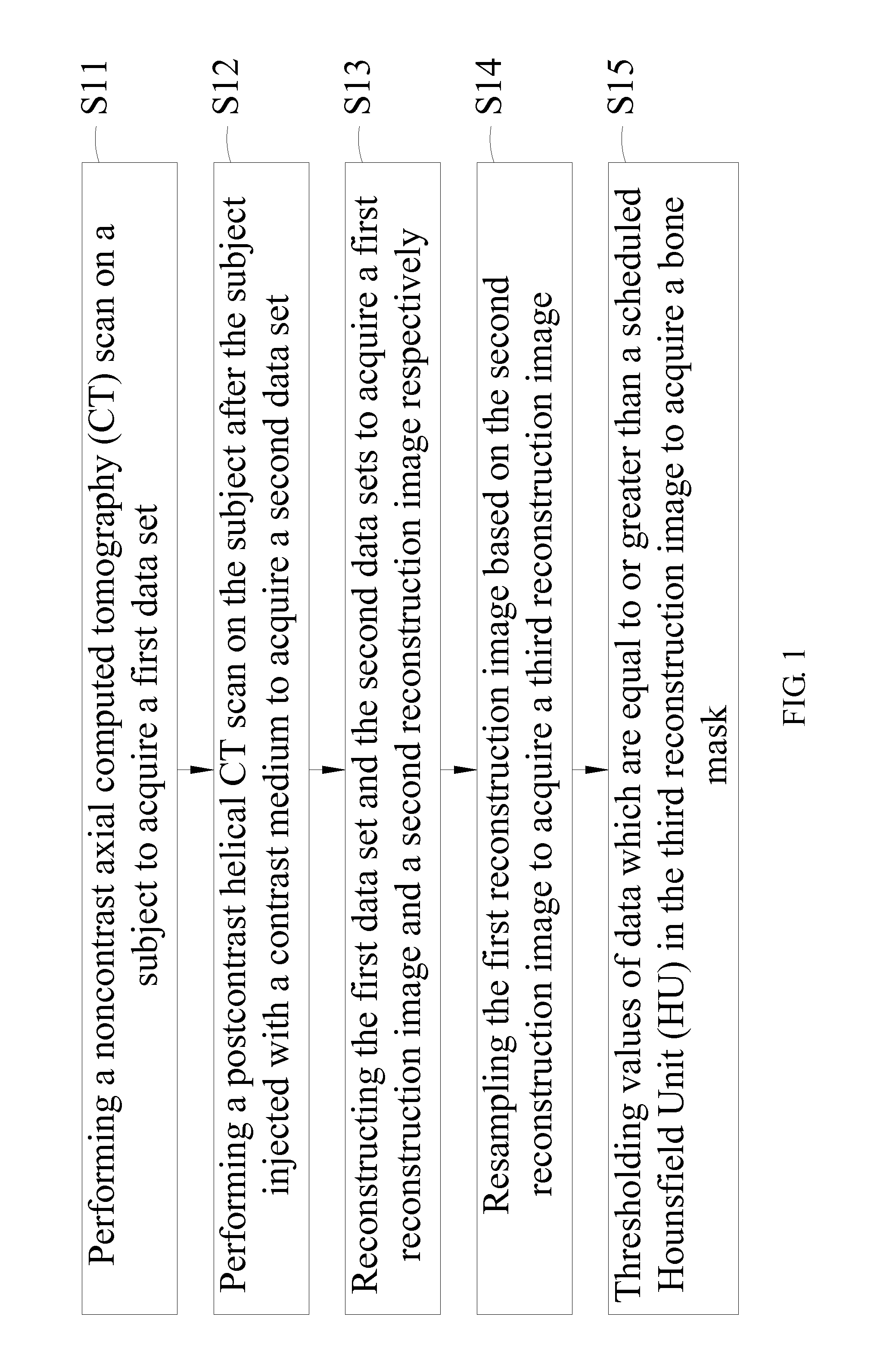
[0031]Please refer to FIG. 1, it is a flowchart of the present invention. As indicated by step S11 in the figure, a first data set is acquired by performing a noncontrast (nonenhanced) axial computed tomography (CT) scan on a subject. As indicated by step S12, a second data set is acquired by performing a postcontrast helical CT scan on the subject after the subject injected with a contrast medium. The contrast medium comprises an iodinated contrast medium. As indicated by the step S13, the first data set and the second data set are reconstructed to acquire a first reconstruction image and a second reconstruction image respectively, in which the second reconstruction image possesses a predetermined spatial resolution. The predetermined spatial resolution may be defined by the predetermined pixel size, by the slice thickness and by the pattern corresponding to the pixel. Once reconstructed, the reconstruction images reveal internal features of a patient. As indicated by step S14, a t...

second embodiment

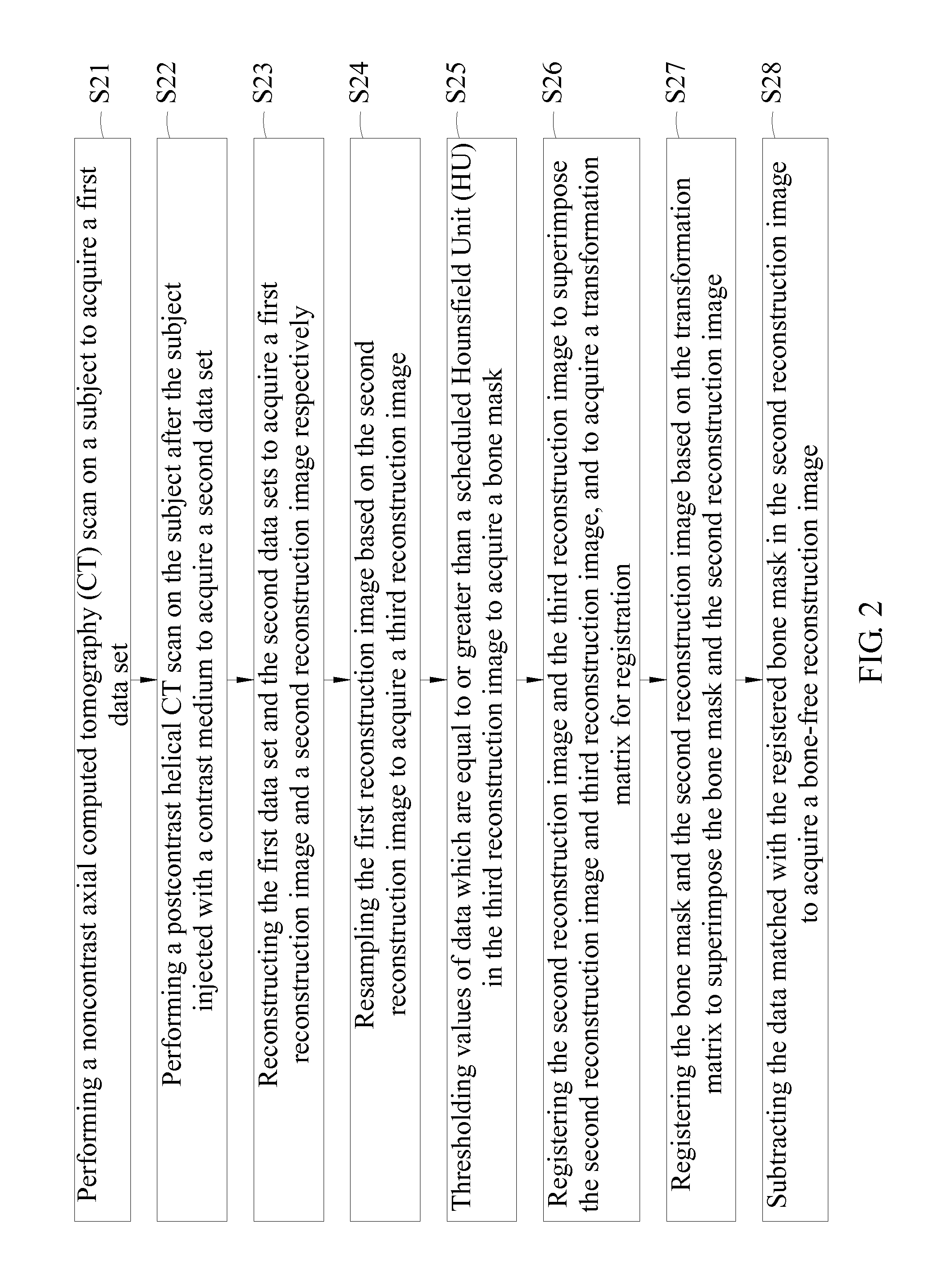
[0032]Please refer to FIG. 2, it is a flowchart of the present invention. As shown in the figure, in the step S21, a first data set is acquired by performing a noncontrast axial computed tomography (CT) scan on a subject. In the step S22, a second data set is acquired by performing a postcontrast helical CT scan on the subject after the subject injected with a contrast medium. As indicated by the step S23, the first data set and the second data set are reconstructed to acquire a first reconstruction image and a second reconstruction image respectively, in which the second reconstruction image possesses a predetermined spatial resolution. As indicated by the step S24, a third reconstruction image is acquired by resampling the first reconstruction image based on the second reconstruction image, such that the third reconstruction image matches the predetermined spatial resolution of the second reconstruction image. As indicated by the step S25, a bone mask is generated by thresholding ...

third embodiment

[0033]Please refer to FIG. 3, it is a flowchart of the present invention. As indicated by step S31 in the figure, a first data set is acquired by performing a noncontrast axial computed tomography (CT) scan on a subject. In the step S32, a second data set is acquired by performing a postcontrast helical CT scan on the subject after the subject injected with a contrast medium. As indicated by the step S33, the first data set and the second data set are reconstructed to acquire a first reconstruction image and a second reconstruction image respectively, in which the second reconstruction image possesses a predetermined spatial resolution. In the step S34, a third reconstruction image is acquired by resampling the first reconstruction image based on the second reconstruction image, such that the third reconstruction image matches the predetermined spatial resolution of the second reconstruction image. As indicated by the step S35, a bone mask is generated by thresholding values of data...


PUM


Abstract

The present invention discloses a method for generating a bone mask. The method comprises the following steps: performing a noncontrast computed tomography scan on a subject in axial mode to get a first data set; after the subject injected with a contrast medium, performing a postcontrast computer tomography angiography scanning on the subject in helical mode to get a second data set; reconstructing the two mentioned data set to acquire a first reconstruction image and a second reconstruction image respectively; resampling the first reconstruction image based on the second reconstruction image by using a computer to get a third reconstruction image; and thresholding values of data which are greater than or equal to a scheduled Hounsfield unit in the third reconstruction image to get a bone mask.

Description

BACKGROUND OF THE INVENTION[0001]1. Field of the Invention[0002]The present invention relates to the field of computed tomography (CT) scan, and more specifically to a method for generating a bone mask by utilizing the images from the standard nonenhanced CT in axial mode scan.[0003]2. Description of Related Art[0004]Being a well-established and fully developed technique, computed tomography angiography (CTA) can be used for the detections of cerebral aneurysms, artery stenoses and other vascular anomalies. Comparing to the conventional angiography, this technique is less invasive. Furthermore, comparing to the magnetic resonance angiography (MRA), CTA has the advantage of having a shorter examination time, a lower cost and loosened screening criteria for patient suitability. Therefore, in the acute setting, CTA is performed frequently for diagnosing vascular diseases. Although three-dimensional visualization and computer-aided analytic techniques such as maximum intensity projectio...

Claims


Application Information

Patent Timeline
Patent Type & Authority Applications(United States)
IPC IPC(8): G06K9/00
CPCG06T7/0026G06T7/0081G06T7/0097G06T2207/30016G06T2207/20016G06T2207/20148G06T2207/10081G06T7/11G06T7/136G06T7/174G06T7/32
Inventor HUANG, HUI-YANGYANG, CHUNG-YILEE, CHUNG-WEILIU, HON-MAN
Owner NAT CENT UNIV
Why Eureka
Try Eureka