Polymer Optical Waveguide Current Sensor

a current sensor and optical waveguide technology, applied in the field of polymer optical waveguide current sensors, can solve the problems of high cost of components required for forming limited application of optical sensors for measuring current, and high cost of optical components forming sensors. achieve the effect of reducing cost, high cost efficiency and reducing cos

Inactive Publication Date: 2012-05-17
PUSAN NAT UNIV IND UNIV COOPERATION FOUND +1
View PDF6 Cites 42 Cited by
  • Summary
  • Abstract
  • Description
  • Claims
  • Application Information

AI Technical Summary

Benefits of technology

[0030]According to the present disclosure, various optical elements having different functions required for an optical sensor for measuring current may be realized on a single substrate through a series of operations. Therefore, it is possible to realize a current-specific optical sensor operating stably regardless of a change in temperature and vibration by adopting polymer optical waveguide technology amenable to mass production with high cost efficiency.
[0031]The optical sensors using optical fibers according to the related art are disadvantageous in that they use expensive components and require a complicated process for assembling the components and producing sensors. On the contrary, the optical current sensor based on integrated-optic technology disclosed herein enables mass production of chips having identical functions on a single substrate through a series of processing operations by introducing an integrated circuit fabrication process. As a result, it is possible to reduce cost required for manufacturing optical current sensors and to extend the spectrum of applications thereof.
[0032]In addition, it is possible to realize hybrid type integrated optical current sensors using optical fiber elements as economical products through the simplification of manufacturing processes and constitutional parts as compared to the existing optical fiber type current sensors.

Problems solved by technology

However, optical sensors for measuring current have been limited in their applications despite the above-mentioned advantages because optical components forming the sensors are expensive.
However, the components required for forming optical sensors for measuring current are still expensive.
However, there is a problem in that polarization may also be changed by a change in surrounding temperatures or vibration of optical fibers.
This may result in a complicated system and an increase in cost.
However, JP 2000-039258 does not suggest any method for integrating all components forming optical current sensors on a single chip.
Moreover, a limited number of optical components may be realized in the above-mentioned manner.
However, the related art does not suggest or disclose about integration of optical components.

Method used


Image

  • Polymer Optical Waveguide Current Sensor
  • Polymer Optical Waveguide Current Sensor
  • Polymer Optical Waveguide Current Sensor

Examples


Embodiment Construction

[0039]

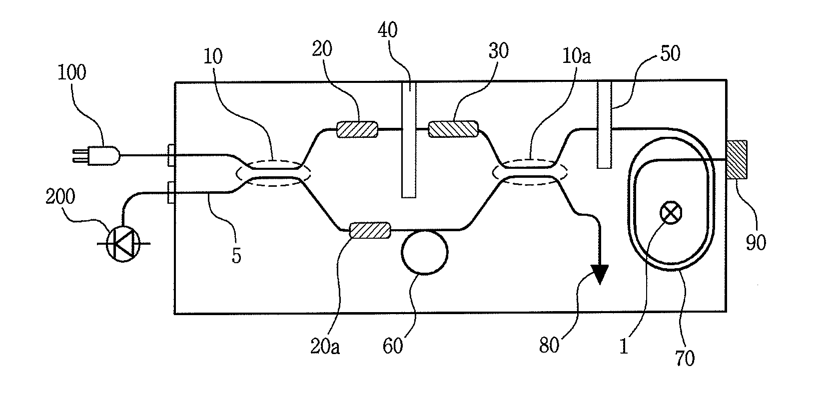
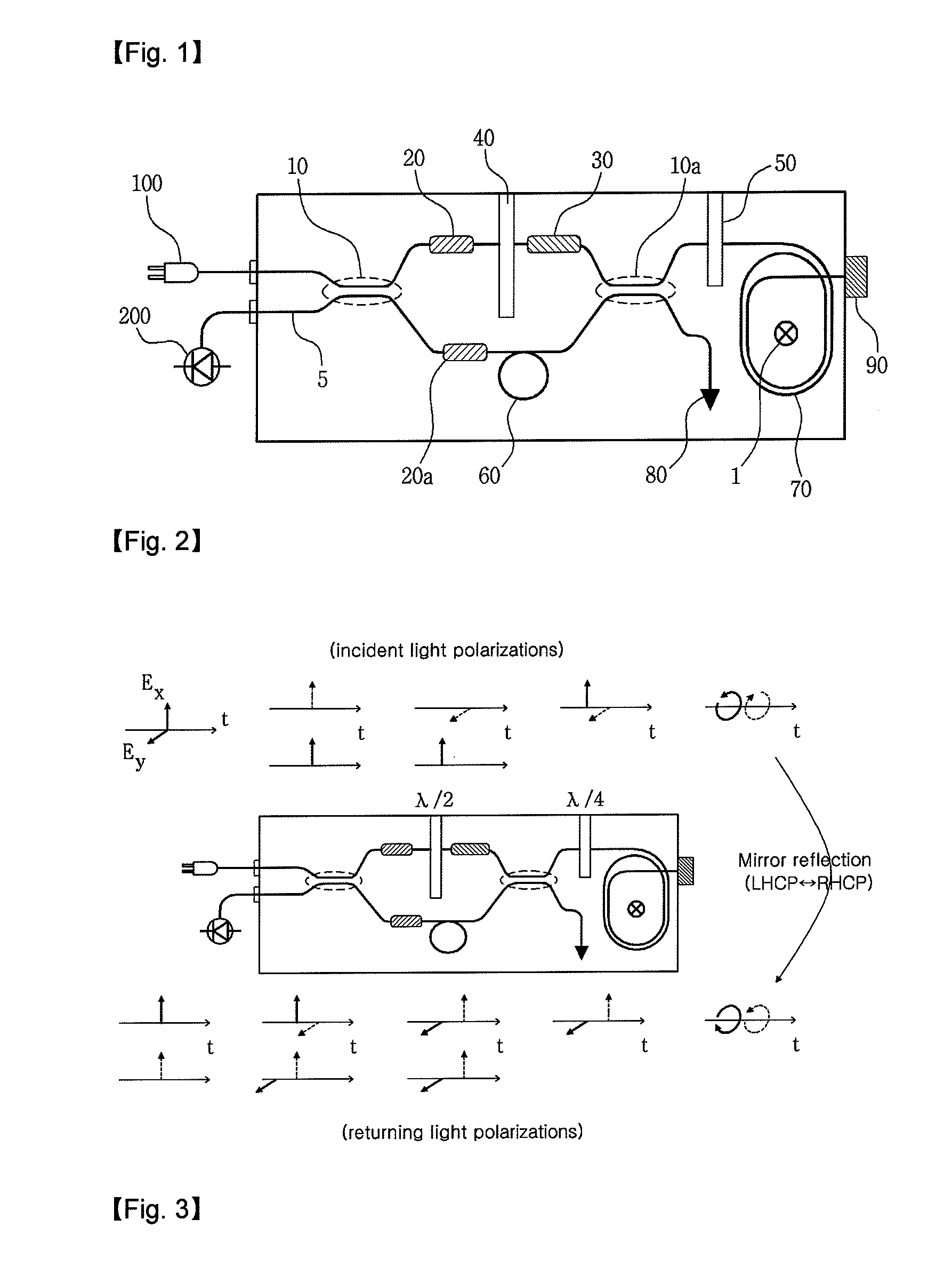
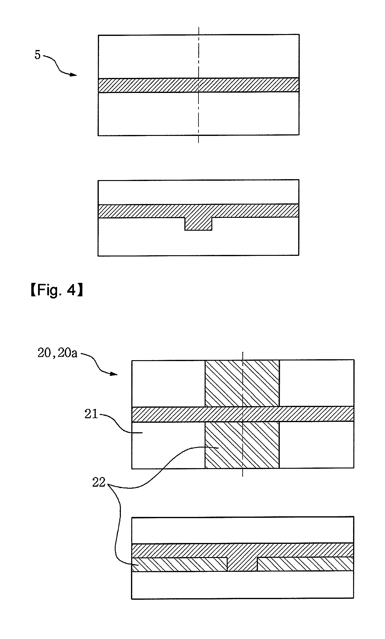
10: optical coupler20: optical waveguide polarizer30: phase modulator40: linear polarization converter50: circular polarization converter60: delay line70: current sensing optical fiber coil80: optical attenuator90: reflection mirror100: light source

BEST MODE

[0040]First, the basic principle of the operation of an optical sensor for measuring current will be described. The optical sensor measures a change in polarization of light waves propagating through an optical waveguide, caused by the effect of the magnetic field applied along the direction of optical fibers. Such an interrelation between light waves and the magnetic field is called the Faraday effect, and the linear proportional factor is defined as the Verdet constant. Therefore, a medium having a larger Verdet constant causes a larger change in polarization of light waves under the effect of the applied magnetic field. When applying linear polarization, such a change in polarization of light waves appears in the form of...


PUM

PropertyMeasurementUnit
depthaaaaaaaaaa
phaseaaaaaaaaaa
magnetic fieldaaaaaaaaaa

Abstract

Provided is an integrated optical current sensor for measuring the magnitude of current. The integrated optical current sensor is fabricated by integrating optical elements, such as a thermo-optic phase modulator, a waveguide polarizer and an optical coupler, on a single substrate. As compared to the known current sensors using optical fibers, the integrated optical current sensor is more compact and enables measurement of current with higher reliability. Provided also is a method for producing current sensor chips in a large scale by using a process for fabricating integrated optical elements.

Description

TECHNICAL FIELD[0001]The present disclosure relates to a polymer optical waveguide current sensor, and more particularly, to an integrated optical waveguide current sensor that may be obtained by integrating optical waveguide elements fabricated on the basis of polymer optical waveguide technology on a single chip.BACKGROUND ART[0002]In general, optical sensors for measuring current have been fabricated by using optical fibers. Such optical sensors for measuring current are characterized in that they enable non-contact current measurement while not causing any change in properties of an electric circuit through which current flows. As compared to hall effect sensors used widely as non-contact measuring sensors, optical sensors for measuring current are advantageous in that they prevent interference caused by electromagnetic waves existing always around a system using high current and enable precise current measurement.[0003]However, optical sensors for measuring current have been li...

Claims


Application Information

Patent Timeline
Patent Type & Authority Applications(United States)
IPC IPC(8): G02F1/01
CPCG01R15/246
Inventor OH, MIN-CHEOL
Owner PUSAN NAT UNIV IND UNIV COOPERATION FOUND
Why Eureka
Try Eureka