Method for producing rare-earth magnets, and slurry application device

Active Publication Date: 2018-05-03
SHIN ETSU CHEM IND CO LTD
View PDF1 Cites 6 Cited by
  • Summary
  • Abstract
  • Description
  • Claims
  • Application Information

AI Technical Summary

Benefits of technology

[0023]Since a plurality of sintered magnet bodies are conveyed by a conveyor and continuously coated with a slurry, the invention is capable of efficient slurry application and amenable to mass production. When the sintered magnet bodies are immersed in the slurry and coated therewith, the sintered magnet bodies are temporarily pushed up. The immersion coating is performed while the sintered magnet bodies are separated apart from the conveyor belt, so that the sintered magnet bodies are properly coated over their entire surfaces with the slurry. Accordingly, the invention can form a uniform dense powder coating in tight bond and is highly efficient and good in mass production.
[0024]In addition, according to the producing method and application device of the invention, the sintered magnet bodies are uniformly coated over the entire surfaces with the rare earth compound powder and the coating step is carried out quite efficiently. Rare earth magnet having improved magnetic properties including a fully increased coercivity can be efficiently produced.
[0025]FIG. 1 is a schematic view showing an application device in one embodiment of the invention.
[0026]FI

Problems solved by technology

This inversely means that if a portion of magnet is not fully coated with the powder, the desired effect is not available at that

Method used


Image

  • Method for producing rare-earth magnets, and slurry application device
  • Method for producing rare-earth magnets, and slurry application device

Examples


example 1

[0053]A thin plate of alloy was prepared by a so-called strip casting technique, specifically by weighing amounts of Nd, Al, Fe and Cu metals having a purity of at least 99 wt %, Si having a purity of 99.99 wt %, and ferroboron, high-frequency heating in argon atmosphere for melting, and casting the alloy melt on a copper single roll in argon atmosphere. The resulting alloy consisted of 14.5 at % Nd, 0.2 at % Cu, 6.2 at % B, 1.0 at % Al, 1.0 at % Si, and the balance of Fe. The alloy was exposed to 0.11 MPa of hydrogen at room temperature for hydriding, and then heated at 500° C. for partial dehydriding while evacuating to vacuum. It is cooled and sieved, obtaining a coarse powder having a size of up to 50 mesh.

[0054]On a jet mill using high-pressure nitrogen gas, the coarse powder was finely pulverized to a weight cumulative median particle size of 5 μm. The resulting fine powder was compacted in a nitrogen atmosphere under a pressure of about 1 ton / cm2 while being oriented in a mag...

example 2

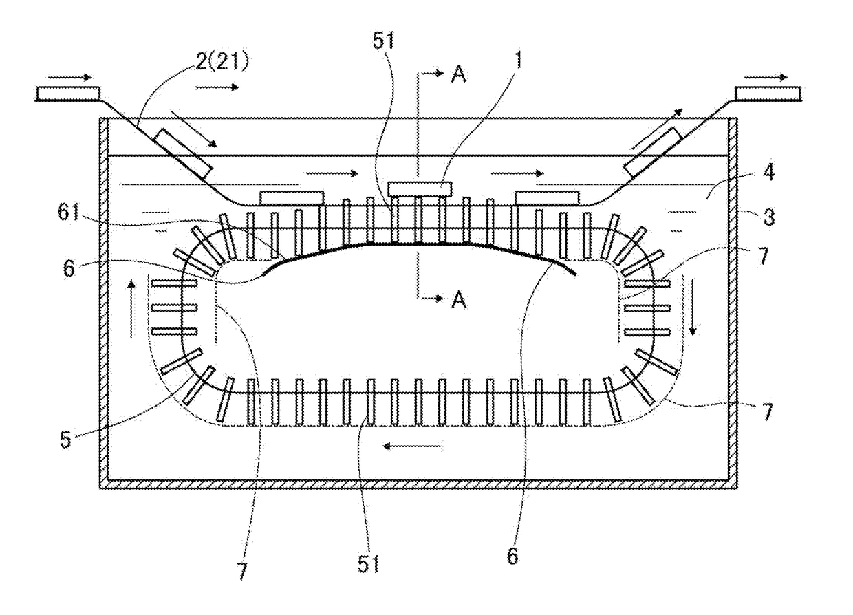
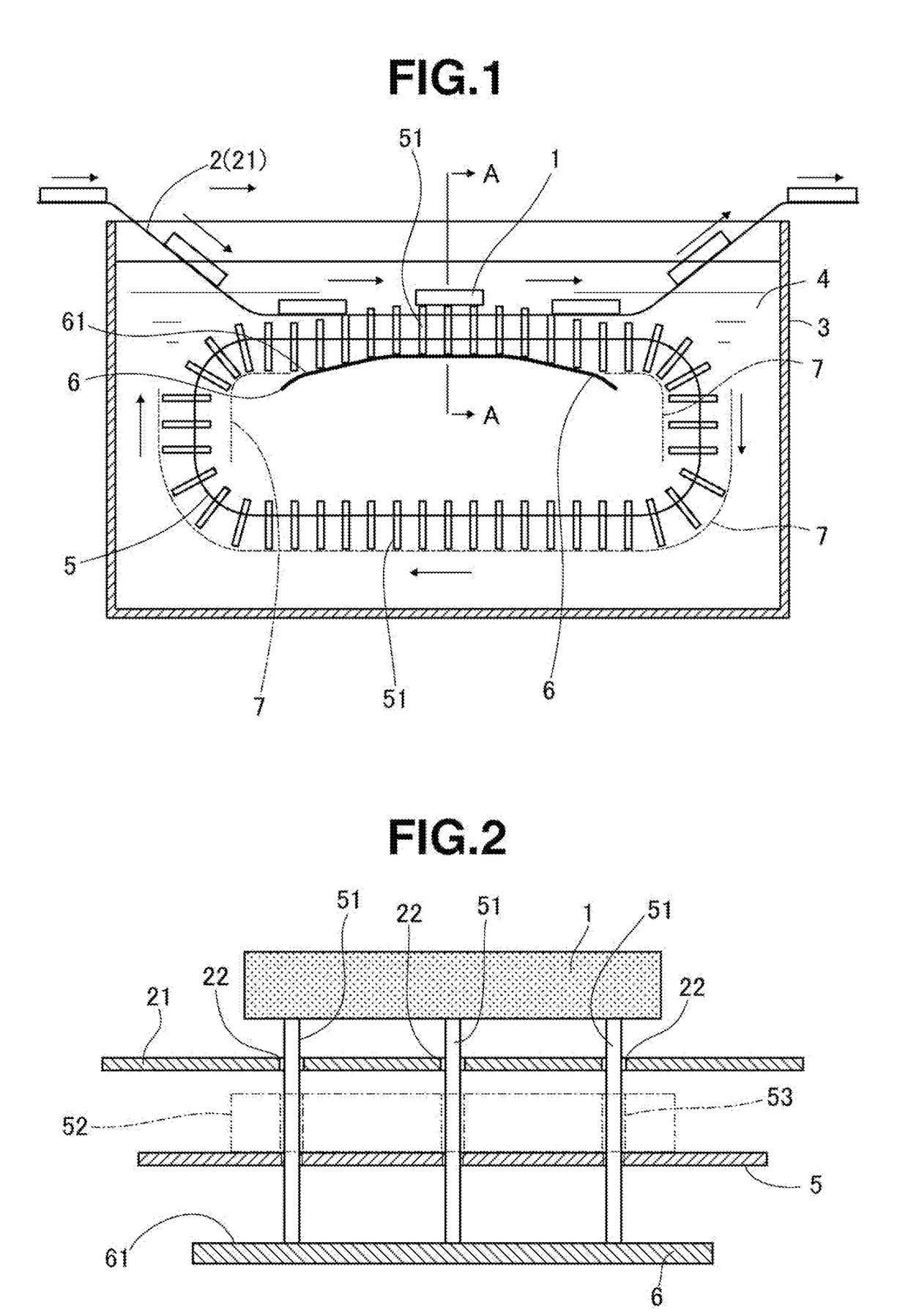
[0062]By the same method as in Example 1 aside from removing all the agitator members 52 from the application device of Example 1, 200 plate-shaped magnet bodies were coated with the slurry. On the surface of all magnet bodies, no color variations indicative of uneven coating were observed.


PUM

PropertyMeasurementUnit
Diameteraaaaaaaaaa

Abstract

When a slurry in which a rare-earth-compound powder is dispersed is applied to sintered magnet bodies 1 and dried to apply the powder thereto, the sintered magnet bodies 1 are conveyed by a conveyer 2 and made to pass through the slurry 4 to apply the slurry to the sintered magnet bodies 1. Furthermore, a plurality of push-up members 51, which pass through insertion holes 22 provided in a conveyor belt 21, and protrude above the conveyor belt, are used to temporarily push up the sintered magnet bodies 1, and temporarily separate the conveyor belt 21 and the sintered magnet bodies 1. As a result, the slurry can be efficiently applied, even mass production can be suitably dealt with, and the slurry can be uniformly and reliably applied to the entire surface of each of the sintered magnet bodies.

Description

TECHNICAL FIELD[0001]This invention relates to a method for producing rare earth magnet by applying a slurry of a rare earth compound-containing powder in a solvent to a sintered magnet body and drying to coat the magnet body with the powder and heat treating for causing the rare earth element to be absorbed in the magnet body, wherein the rare earth compound powder is uniformly and efficiently coated and rare earth magnet having excellent magnetic properties is efficiently produced and a slurry application device suited for use in the rare earth magnet producing method.BACKGROUND ART[0002]Rare earth permanent magnets including Nd—Fe—B base magnets find an ever spreading application owing to their excellent magnetic properties. Methods known in the art for further improving the coercivity of these rare earth magnets include a method for producing a rare earth permanent magnet by coating the surface of a sintered magnet body with a rare earth compound powder, and heat treating the co...

Claims


Application Information

Patent Timeline
IPC IPC(8): H01F41/02H01F1/053H01F1/08C22C38/00B22F9/04B22F3/00
CPCH01F41/0293H01F1/0536H01F1/086C22C38/005B22F9/04B22F3/00B22F2999/00B22F2998/10B05D5/12B05C3/10B05C13/02B05D1/18B22F3/24C22C38/002H01F1/0577B05D2401/10B05D2401/32
Inventor KURIBAYASHI, YUKIHIROKAMIYA, SHOGOMAEGAWA, HARUKAZUTANAKA, SHINTARO
Owner SHIN ETSU CHEM IND CO LTD
Why Eureka
Try Eureka