
Pellicle for lithography

a lithography and pellicle technology, applied in the field of lithography, can solve the problems of poor quality, deformation appearance, lowering the performance and the manufacture yield of semiconductor devices and liquid crystal display boards,

Active Publication Date: 2012-05-17
SHIN ETSU CHEM IND CO LTD
View PDF0 Cites 5 Cited by
  • Summary
  • Abstract
  • Description
  • Claims
  • Application Information

AI Technical Summary

Benefits of technology

[0022]The pellicle for lithography according to the present invention is advantageous in that, inasmuch as the adhesion strength of the agglutinant layer is subdued to the range of 1 N / m through 100 N / m, the deformation of the agglutinant layer caused as the pellicle is attached to the mask under pressure is undone as the pressure is removed, so that the deformation of the mask that accompanies the attachment operation of the pellicle to the mask is effectively restricted.

Problems solved by technology

In manufacturing semiconductor devices such as LSI and super-LSI or in manufacturing a liquid crystal display board or the like, a pattern transferring is conducted by irradiating light to an exposure original plate such as a semiconductor wafer or an original plate for liquid crystal, but if a dust particle exists adhering to the exposure original plate, the dust particle absorbs the light or refracts it, giving rise to deformation of a transferred pattern and roughened edges, which lead to problems such as a damaged dimension, a poor quality and a deformed appearance, lowering the performance and the manufacture yield of the semiconductor devices and the liquid crystal display board.
Thus, these works are usually performed in a clean room, but it is still difficult to keep the exposure original plate in a dust-free state all the time; therefore, a pellicle, which transmits the exposure light well, is attached to a surface of the exposure original plate as a dust-fender.
Under such circumstances, dust does not directly adhere to the surface of the exposure original plate but only onto the pellicle membrane, and thus, in lithography operation, by setting a photo focus on the pattern formed on the exposure original plate, the dust particles on the pellicle membrane fail to cast their shadows in the image transfer performance.
However, as the wavelengths of the exposure lights are shifted toward zero side, a new problem has arisen wherein a deformation of the lithographic image is caused by the deformed flatness of exposure original plate (mask).
It has been pointed out that one of the causes for the deformation of the flatness of the exposure original plate is the less admirable flatness of the pellicle which is attached to the exposure original plate.

Method used


Image

  • Pellicle for lithography
  • Pellicle for lithography
  • Pellicle for lithography

Examples


example 1

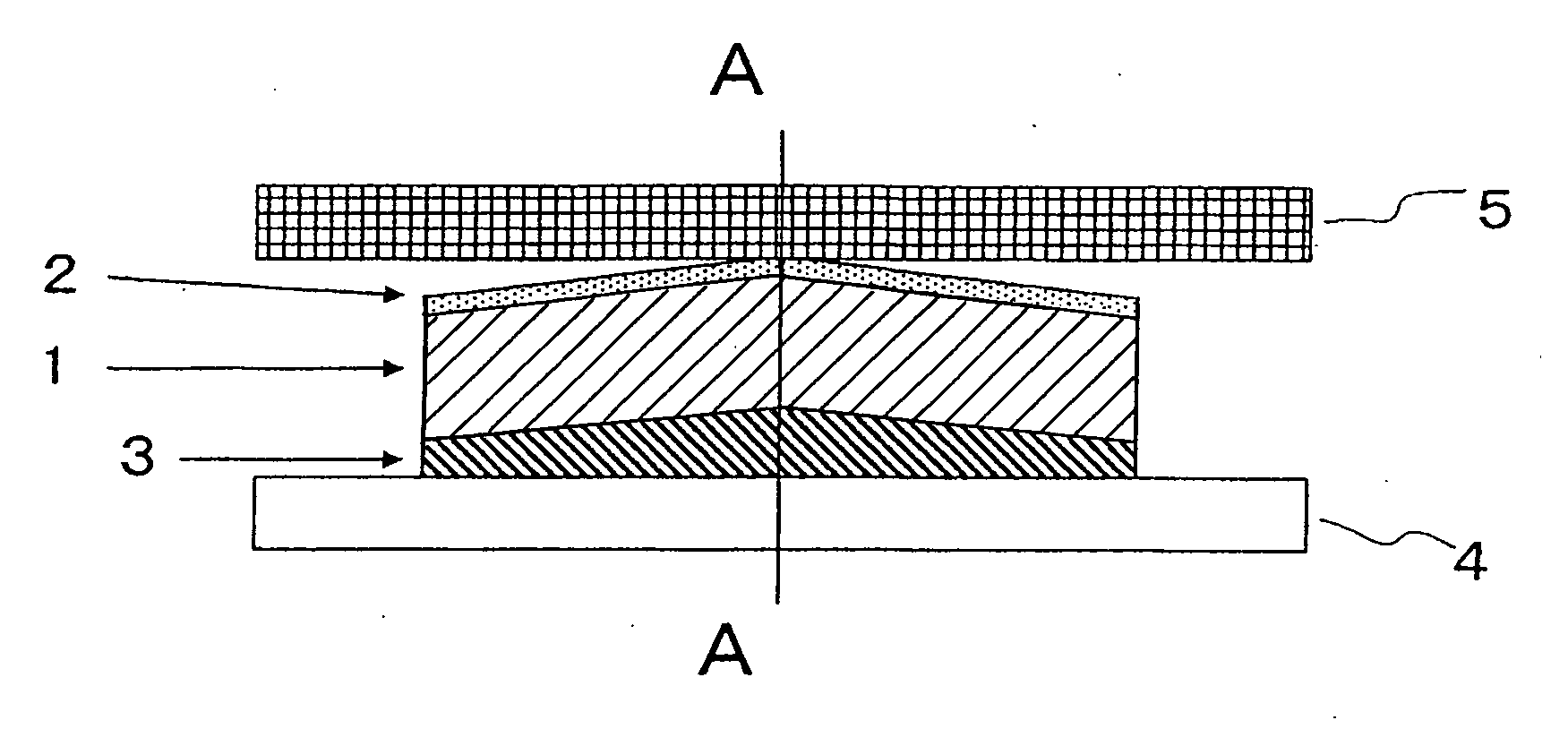
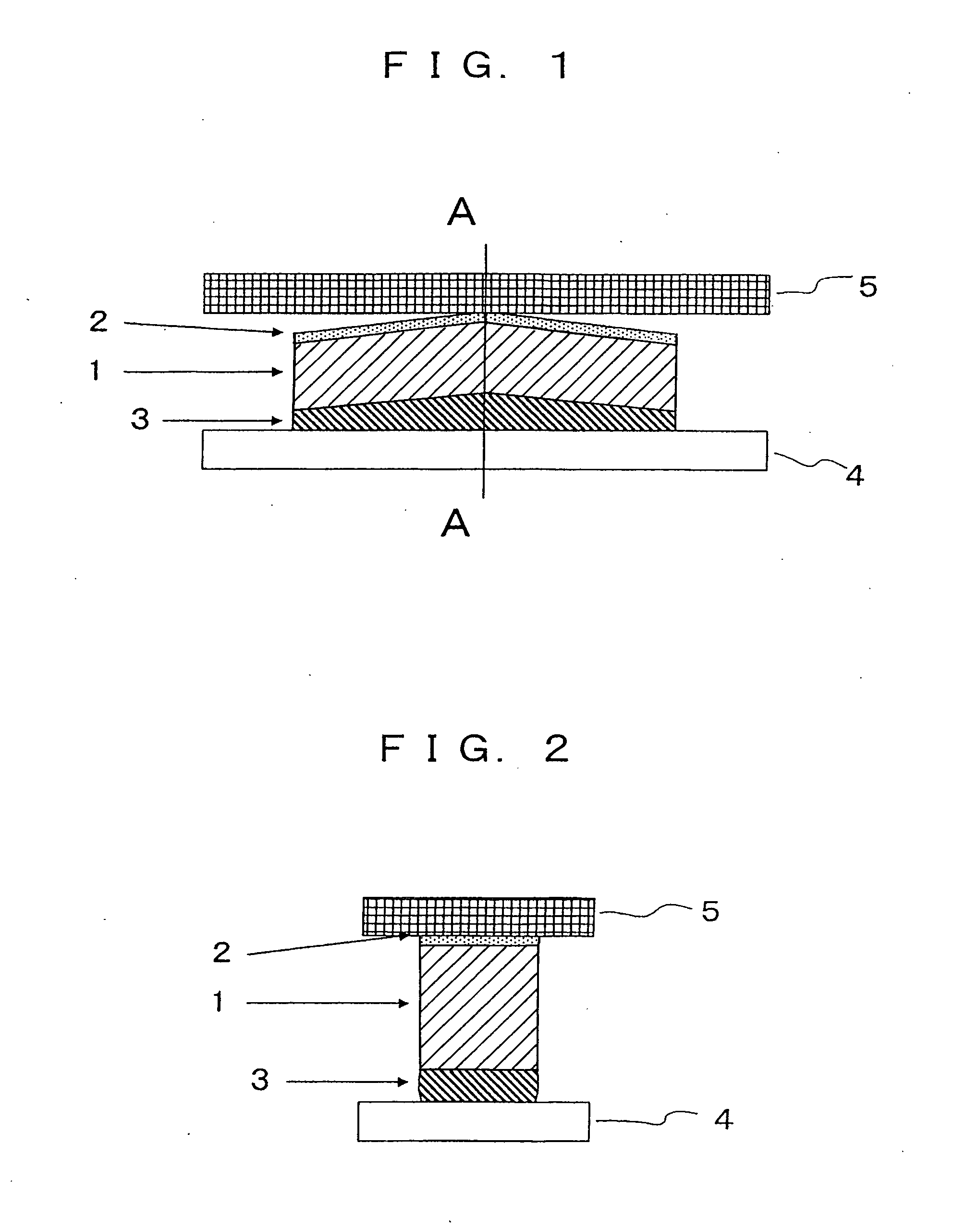
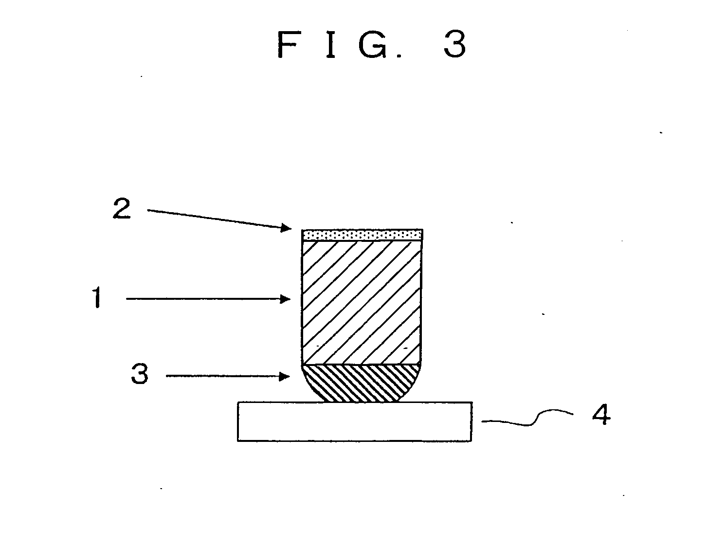
[0034]A pellicle frame made of an aluminum alloy (outer dimension being 149 mm×113 mm×4.5 mm, the frame width 2 mm, flatness of both the agglutinant-side and the adhesive-side annular faces of the frame 10 micrometers) was washed in pure water, and an acrylic resin agglutinant SK-Dyne 1495 (a commercial product of Soken Chemical & Engineering Co., Ltd.) was applied to the agglutinant-side annular face of the frame and was let to sit for one hour at room temperature. A separator was laid on a surface of a quartz glass plate having a flatness of 3 micrometers, and the pellicle frame was placed on it with the agglutinant layer lying on the quartz glass plate surface via the separator. Thus the agglutinant layer on the pellicle frame was molded to have a flat face. Thereafter, the quartz glass plate was heated and kept at 70 degrees centigrade for 12 hours whereby the agglutinant was precured. After this precuring of the agglutinant, the frame was removed from the quartz glass plate and...

example 2

[0041]A pellicle frame made of an aluminum alloy (outer dimension being 149 mm×113 mm×4.5 mm, the frame width 2 mm, flatness of both the agglutinant- and the adhesive-side annular faces of the frame 10 micrometers) was washed in pure water, and an acrylic resin agglutinant Corponyl 2260 (a commercial product of The Nippon Synthetic Chemical Industry Co., Ltd.) was applied to the agglutinant-side annular face of the frame and was let to sit for one hour at room temperature. A separator was laid on a surface of a quartz glass plate having a flatness of 3 micrometers, and the pellicle frame was placed on it with the agglutinant layer lying on the quartz glass plate surface via the separator. Thus the agglutinant layer on the pellicle frame was molded to have a flat face. Thereafter, the quartz glass plate was heated and kept at 70 degrees centigrade for 12 hours whereby the agglutinant was precured. After this precuring of the agglutinant, the frame was removed from the quartz glass pl...

example 3

[0046]A pellicle frame made of an aluminum alloy (outer dimension being 149 mm×113 mm×4.5 mm, the frame width 2 mm, flatness of both the agglutinant- and the adhesive-side annular faces of the frame 10 micrometers) was washed in pure water, and an acrylic resin agglutinant SK-Dyne 1499 (a commercial product of Soken Chemical & Engineering Co., Ltd.) was applied to the agglutinant-side annular face of the frame and was let to sit for one hour at room temperature. A separator was laid on a surface of a quartz glass plate having a flatness of 3 micrometers, and the pellicle frame was placed on it with the agglutinant layer lying on the quartz glass plate surface via the separator. Thus the agglutinant layer on the pellicle frame was molded to have a flat face. Thereafter, the quartz glass plate was heated and kept at 70 degrees centigrade for 12 hours whereby the agglutinant was precured. After this precuring of the agglutinant, the frame was removed from the quartz glass plate and the...


PUM


Abstract

There is provided a pellicle in which the mask-bonding agglutinant layer has the adhesion strength of 1 N / m through 100 N / m, preferably 4 N / m through 80 N / m, and more preferably the agglutinant layer has a facial flatness of 15 micrometers or smaller, and still more preferably the membrane-bonding adhesive layer has a facial flatness of 15 micrometers or smaller: for the purpose of better preventing the pellicle frame from affecting the mask to deform.

Description

[0001]The present non-provisional application claims priority, as per Paris Convention, from Japanese Application No. 2010-256482 filed on Nov. 17, 2010, the disclosure of which is hereby incorporated by reference herein in its entirety.FIELD OF THE INVENTION[0002]This invention concerns a pellicle for lithography used as a dust-fender employed in lithographic printing to manufacture semiconductor devices especially such as LSI and super LSI.TECHNICAL BACKGROUND OF THE INVENTION[0003]In manufacturing semiconductor devices such as LSI and super-LSI or in manufacturing a liquid crystal display board or the like, a pattern transferring is conducted by irradiating light to an exposure original plate such as a semiconductor wafer or an original plate for liquid crystal, but if a dust particle exists adhering to the exposure original plate, the dust particle absorbs the light or refracts it, giving rise to deformation of a transferred pattern and roughened edges, which lead to problems su...

Claims


Application Information

Patent Timeline
IPC IPC(8): G03F1/64
CPCG03F1/64G03F1/62H01L21/027
Inventor SHIRASAKI, TORU
Owner SHIN ETSU CHEM IND CO LTD
Learn More