Independent carrier ethernet interconnection platform

a carrier ethernet and platform technology, applied in the field of data transmission, can solve the problems of slowing carrier ethernet adoption for years to come, unable to significantly mitigate the time, resources, cost and coordination of actually implementing nni interconnection, etc., to achieve scalable carrier ethernet interconnection, facilitate standards-based provisioning, and facilitate the effect of standard-based provisioning

Inactive Publication Date: 2012-05-17
CENX
View PDF3 Cites 15 Cited by
  • Summary
  • Abstract
  • Description
  • Claims
  • Application Information

AI Technical Summary

Benefits of technology

[0016]The present invention is intended to solve the above-noted business and technical problems by establishing an independent, common service provider interconnection platform with advanced switching capabilities and centralized monitoring to enable the rapid, efficient provisioning of Carrier Ethernet services between multiple service providers' networks. This invention both facilitates standards based, scalable Carrier Ethernet interconnection while also enabling service providers with incompatible services to readily interconnect through the use of advanced, proprietary network management capabilities.

Problems solved by technology

Creating Ethernet NNI interconnection standards has taken several years due to the vast differences and incompatibilities between service providers' networks, systems and services.
This MEF 26 standard, however, does not, of course, significantly mitigate the time, resources, cost and coordination of actually implementing the NNI interconnection.
The significant differences between service providers' network, systems and services will still make implementation of the NNI standards a very extensive effort that could take years to complete, potentially slowing Carrier Ethernet adoption for years to come.
The costs, delays, and challenges of such NNI interconnections have made this a limited option.
While this effort potentially creates a physical bonding between the service providers, this physical cross-connection is on a one to one service provider basis, thus not offering scalability to reach more than one service provider through a single connection; moreover, just establishing a physical bond is almost always insufficient to allow end-to-end Ethernet Service connectivity between the providers.
Moreover, changing such configurations causes considerable work on the part of the provider; testing these configurations, training staff, updating procedural documents and updating Operational Support Systems.
While most collocation or carrier hotels do not provide interconnection functions beyond their “Meet Me” cross-connect panels, a limited number of collocation centers do provide some in-facility networking to enable one service provider in the facility to reach other service providers for interconnection purposes.
Such simple intra-facility functionality does reduce the number of costly physical connections but offers little to address the Ethernet Service Mapping challenges.
Again, each Ethernet carrier has different systems and equipment for measuring quality of service, so it is complex to do so across a large number of carriers and does not scale well.
Finally, even if interconnections are achieved and monitoring is employed, there are differences between each carrier's system and process for querying service, building inventory, quotations, ordering, fulfillment, service legal agreement (SLA) reporting, trouble sectionalizing, and billing harmonizing.
Thus, bonding these systems would not increase efficiency between carriers.
Finally, there is a significant challenge associated with Service Quality Monitoring.
This is very costly, both because of the cost of this device but also in the fact that the service provider generally does not have people to do installation, support and repair of these devices in every off-net region.

Method used


Image

  • Independent carrier ethernet interconnection platform
  • Independent carrier ethernet interconnection platform
  • Independent carrier ethernet interconnection platform

Examples


Embodiment Construction

[0033]While the present invention may be embodied in various forms, there is shown in the drawings and will hereinafter be described some exemplary and non-limiting embodiments, with the understanding that the present disclosure is to be considered an exemplification of the invention and is not intended to limit the invention to the specific embodiments illustrated.

[0034]In this application, the use of the disjunctive is intended to include the conjunctive. The use of definite or indefinite articles is not intended to indicate cardinality. In particular, a reference to “the” object or “a” and “an” object is intended to denote also one of a possible plurality of such objects.

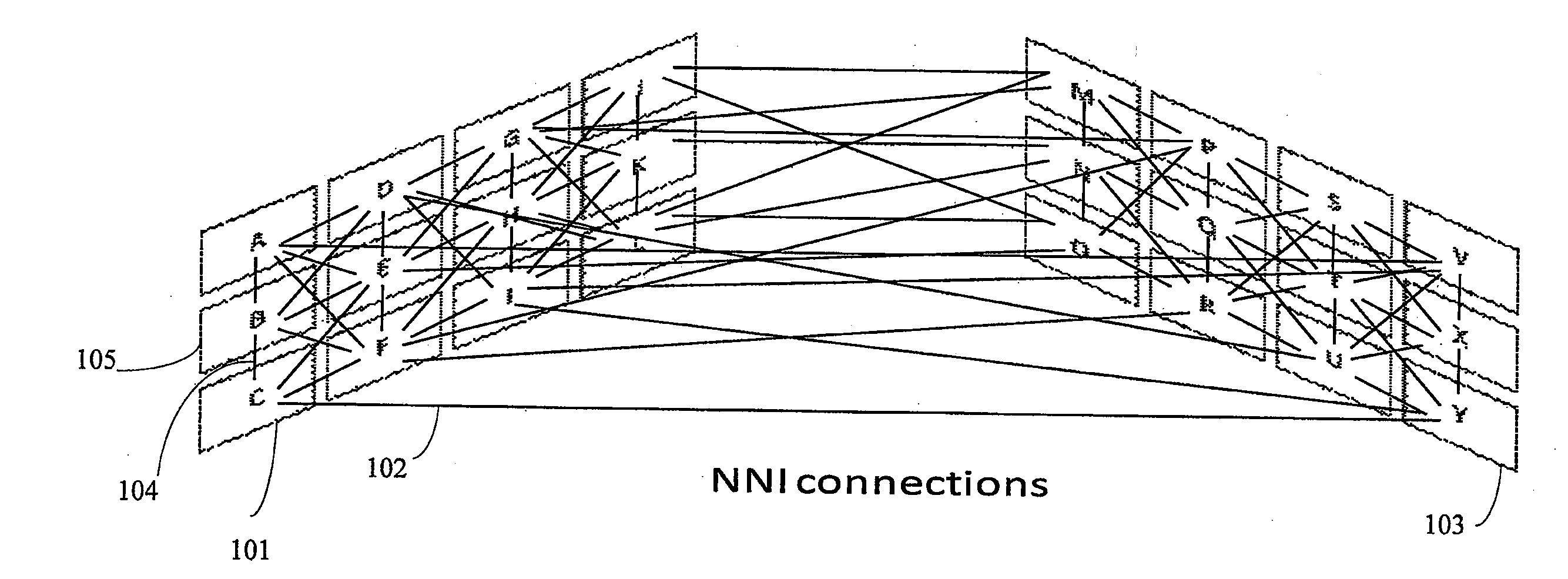
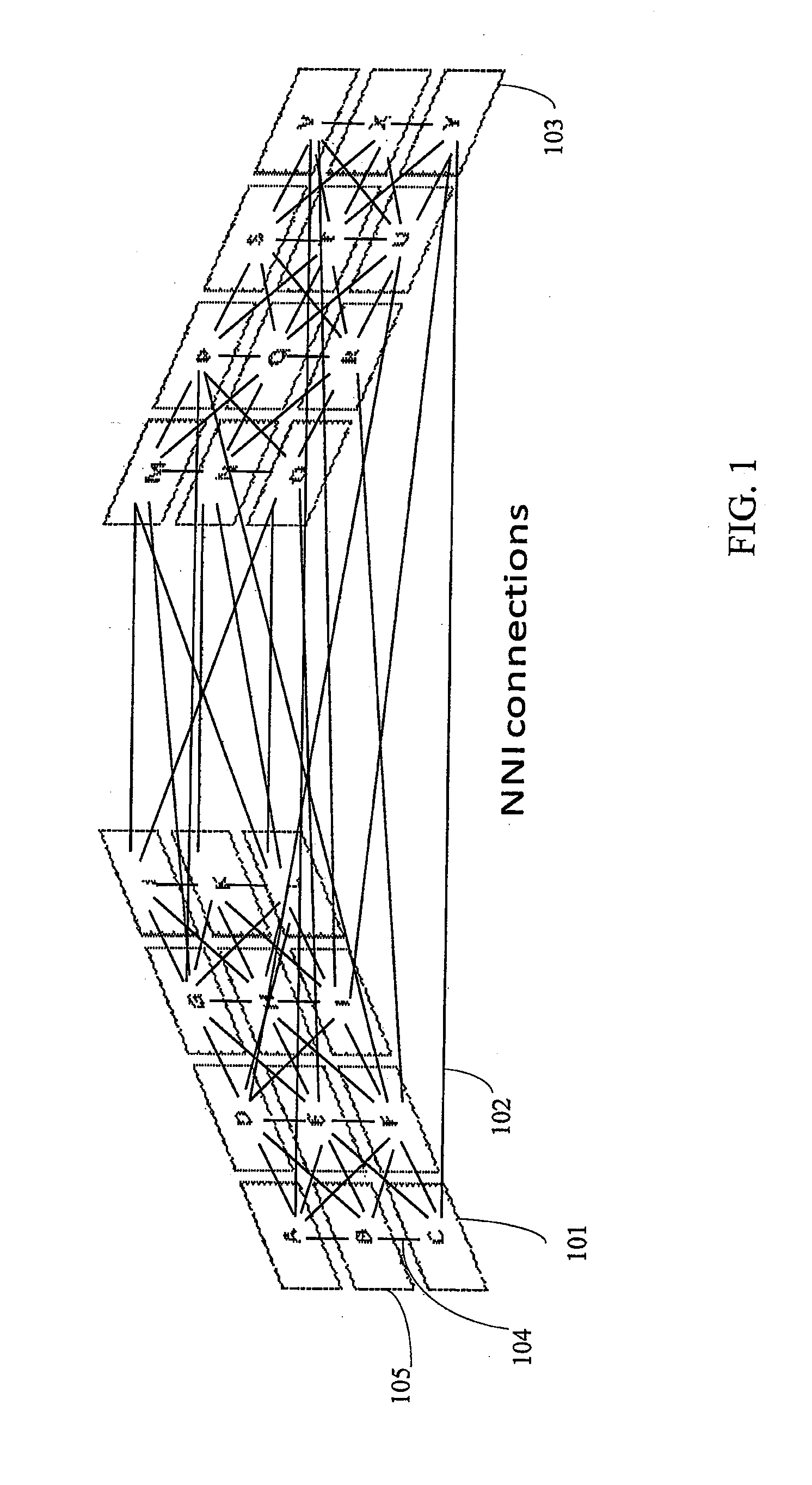
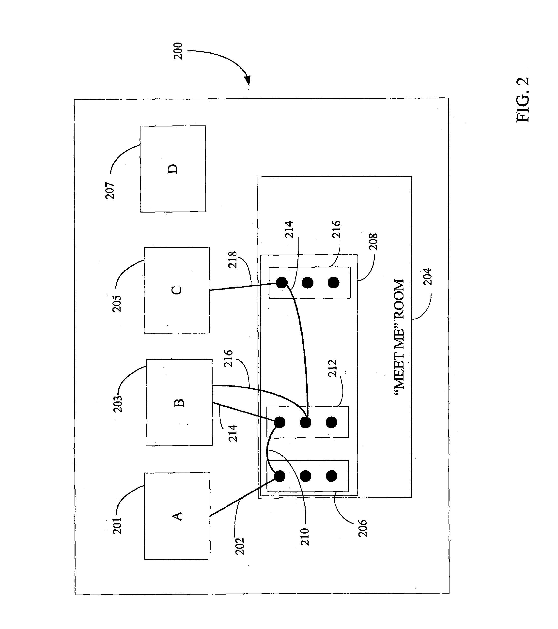
[0035]A preferred embodiment of the present invention provides a first service-level interconnect platform designed to join disparate service provider networks in order to enable end-to-end Carrier Ethernet across service providers' networks. Conventionally, an expansion of Carrier Ethernet has been constrained, ...


PUM


Abstract

A communications system is provided for enabling a plurality of service providers to interconnect via an Ethernet platform, the plurality of service providers employing disparate Ethernet protocols. The system includes a central server and a plurality of switching locations. Each one of the plurality of switching locations is communicatively connected to the central server and to the plurality of service providers. Each of the plurality of switching locations includes a plurality of Ethernet router switches, a monitoring device, a local server coupled to a plurality of databases. Each of the plurality of databases is associated with each of the service providers. A communications media is provided for interconnecting the plurality of switches, the service providers, the router switches, the connectivity device, and the local server. The system enables the service providers to be interconnected on the Ethernet platform by establishing protocol mappings between any two Ethernet protocols associated with corresponding service providers.

Description

CROSS-REFERENCE[0001]This international patent application claims priority to U.S. Provisional Patent Application No. 61 / 230,069 filed on Jul. 30, 2009, which is incorporated by reference herein in its entirety.TECHNICAL FIELD[0002]This invention generally relates to data transmission, and more particularly to an independent, service provider interconnection platform with advanced switching capabilities and centralized monitoring to enable rapid and efficient provisioning of Carrier Ethernet services between multiple service provider networks.BACKGROUND OF THE INVENTION[0003]As service providers strive to increase revenues by integrating new data, voice, and video service offerings, they are also, for efficiency reasons, converging their networks to support these services over a single Internet Protocol (IP) infrastructure. To best enable this convergence, service providers are migrating to Ethernet, a highly efficient technology originally used inside premises, as the connectivity ...

Claims


Application Information

Patent Timeline
Patent Type & Authority Applications(United States)
IPC IPC(8): G06F15/16G06Q30/02G06F15/173G06Q30/00G06Q30/06
CPCG06Q30/0241G06Q30/0601G06Q30/0641H04L69/18H04L12/2854H04L49/351H04L12/2852
Inventor CHEN, ZINANGAVILLET, RONALDPURDY, CHRIS
Owner CENX
Why Eureka
Try Eureka