
Computer system and power management method thereof

Active Publication Date: 2012-05-17
INVENTEC CORP
View PDF4 Cites 12 Cited by
  • Summary
  • Abstract
  • Description
  • Claims
  • Application Information

AI Technical Summary

Benefits of technology

[0008]Accordingly, the present invention is directed to a computer system and a power management method thereof, so that when at least one of the power supplies fails or is damaged, the computer system can still work safely with the optimal performance.
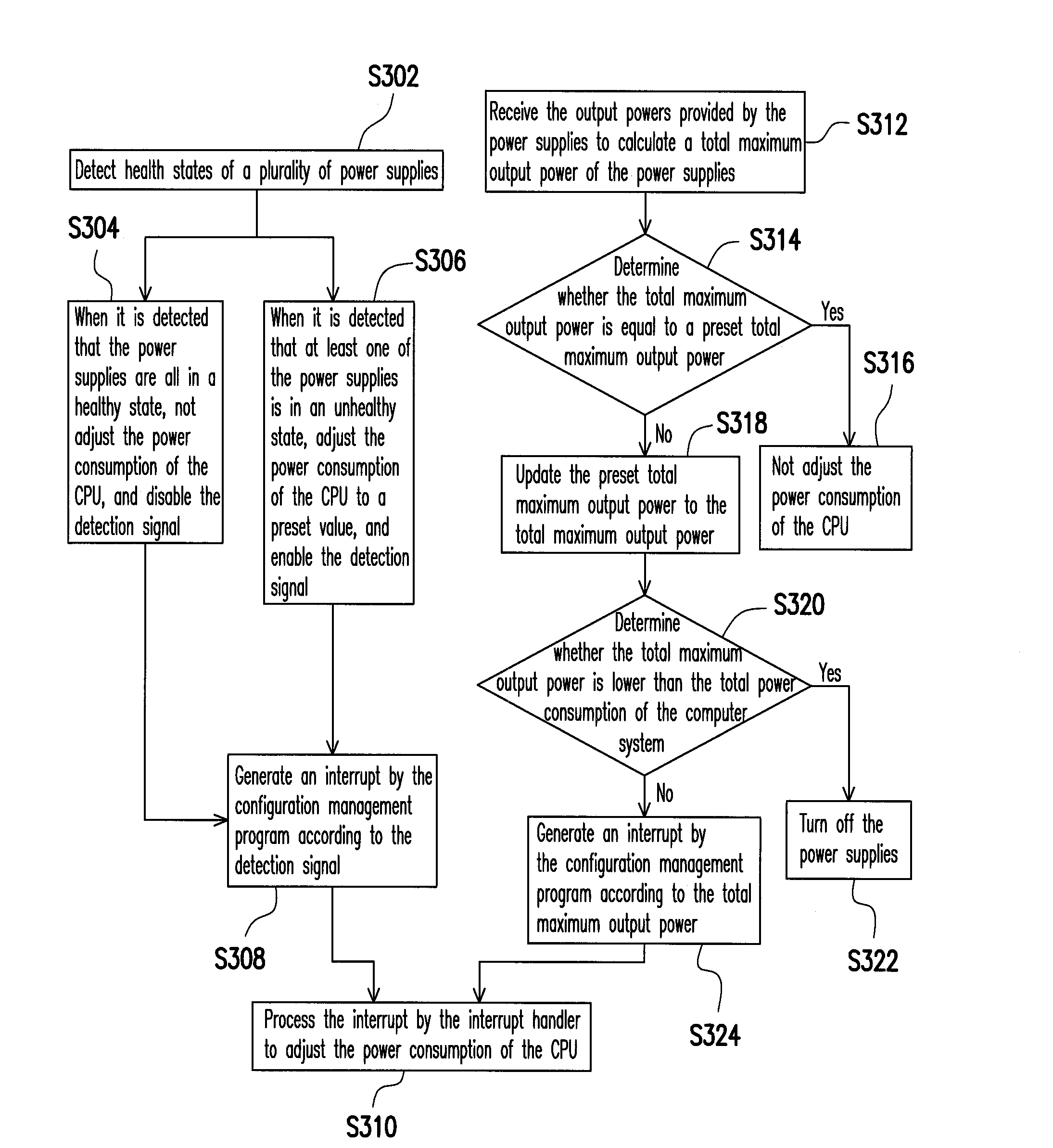
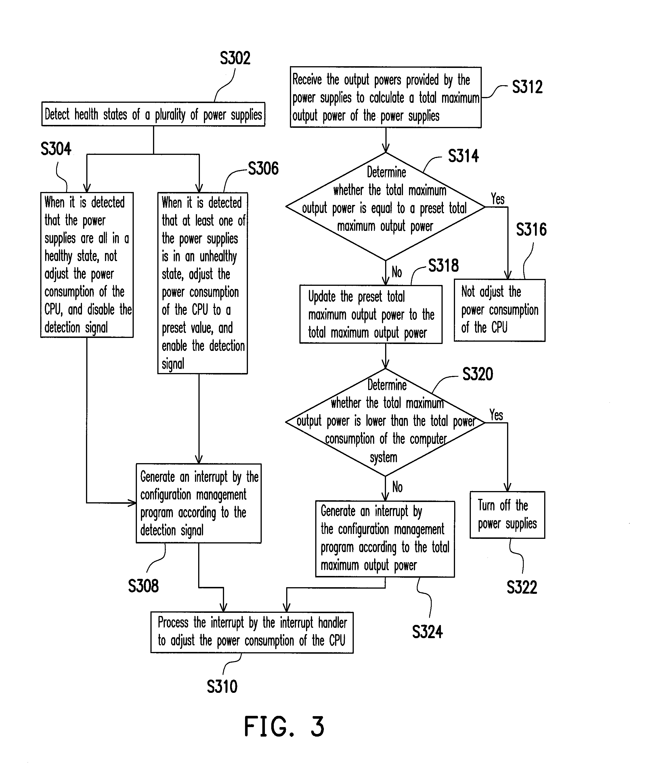
[0020]Next, the interrupt is generated by triggering the configuration management program according to the health states or the total maximum output power of the power supplies. The interrupt is then processed by the interrupt handler to adjust the power consumption of the CPU. In this manner, through the present invention, when at least one of the power supplies fails or is damaged, the computer system can still work safely with the optimal performance. Moreover, the present invention is also capable of predicting the output powers of the power supplies (that is, to predict the changes of the output powers of the power supplies), to accordingly adjust the power consumption of the CPU.

Problems solved by technology

However, in the case that the power supply fails or is damaged (that is, the power supply cannot provide power for the computer system), the power consumption of the computer system may exceed the maximum power that can be provided by the rest of the power supplies.
However, the above adjustment may result in that the current working frequency of the CPU is not optimal, and more power of the power supply is wasted.
Therefore, the computer system cannot dynamically adjust with the actual situation (that is, fails to provide a mechanism of detecting whether the total maximum output power provided by the power supply is sufficient or not), such that when the power provided by the power supply is sufficient, the actuation of the power throttling feature may cause the performance of the computer device to be further deteriorated.

Method used


Image

  • Computer system and power management method thereof
  • Computer system and power management method thereof
  • Computer system and power management method thereof

Examples


Embodiment Construction

[0026]Reference will now be made in detail to the present embodiments of the invention, examples of which are illustrated in the accompanying drawings. Wherever possible, the same reference numbers are used in the drawings and the description to refer to the same or like parts.

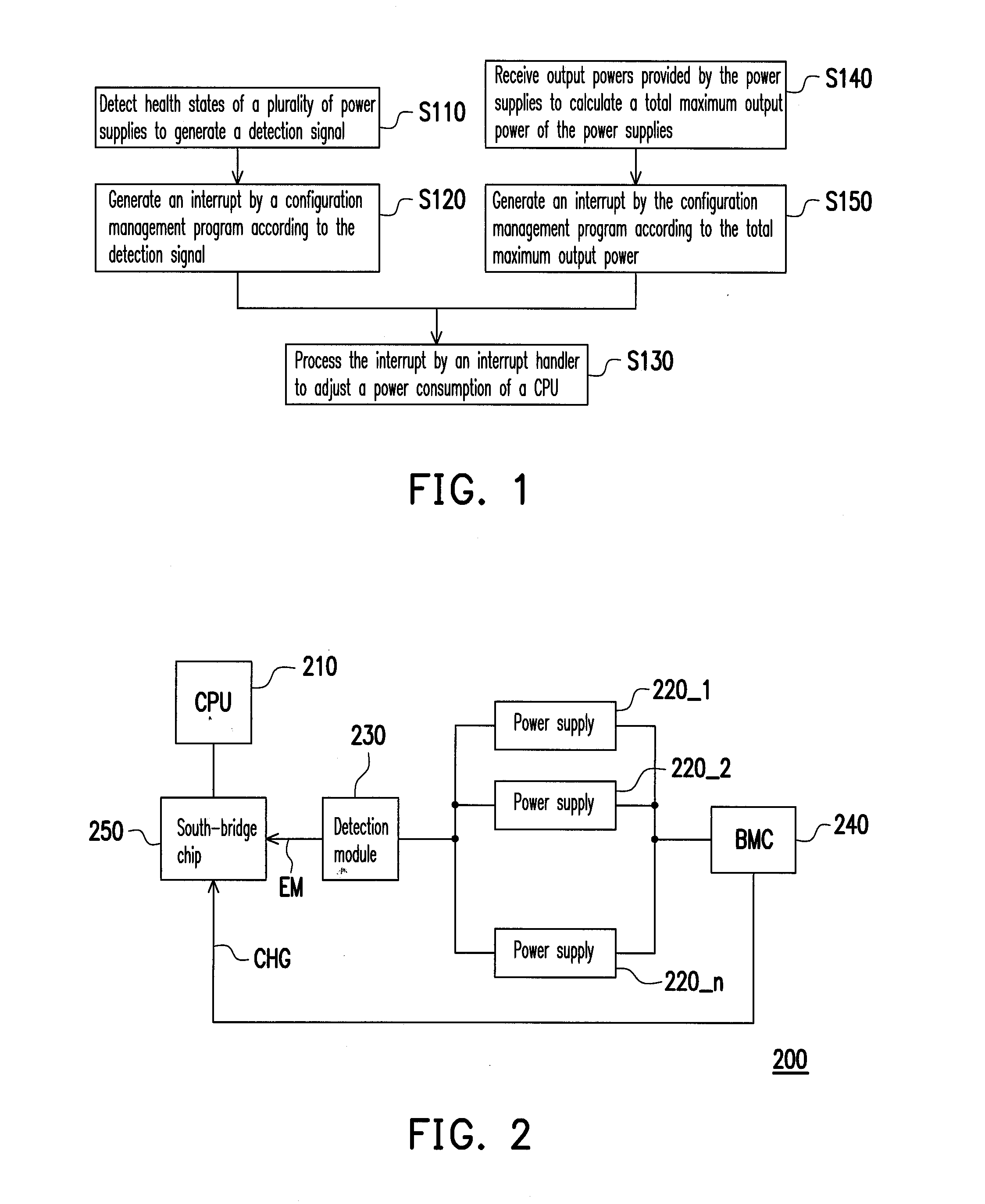
[0027]FIG. 1 is a flow chart of a power management method of a computer system according to an embodiment of the present invention. FIG. 2 is a block diagram of a computer system according to an embodiment of the present invention. Referring to FIG. 2, the computer system 200 includes a CPU 210, a plurality of power supplies 220_1 to 220—n, a detection module 230, a BMC 240, and a south-bridge chip 250, where n is a positive integer larger than 1. The coupling relations between the CPU 210, the power supplies 220_1 to 220—n, the detection module 230, the BMC 240, and the south-bridge chip 250 are as shown in FIG. 2, so the details thereof are not described herein.

[0028]Referring to FIGS. 1 and 2, in Step S110,...


PUM


Abstract

A power management method of a computer system is provided. The method includes the following steps. Health states of a plurality of power supplies are detected to generate a detection signal. Output powers provided by the power supplies are received to calculate a total maximum output power of the power supplies. An interrupt is generated by triggering a configuration management program according to the total maximum output power or the detection signal. The interrupt is processed by an interrupt handler to adjust a power consumption of a central processing unit (CPU).

Description

CROSS-REFERENCE TO RELATED APPLICATION[0001]This application claims the priority benefit of Taiwan application serial no. 99138888, filed on Nov. 11, 2010. The entirety of the above-mentioned patent application is hereby incorporated by reference herein and made a part of this specification.BACKGROUND OF THE INVENTION[0002]1. Field of the Invention[0003]The present invention generally relates to a power management method, in particular, to a computer system and a power management method thereof.[0004]2. Description of Related Art[0005]Generally, a plurality of power supplies is configured in some computer system, to provide the computer system with enough electric power for normal working, in which some of the power supplies serve as backup power. However, in the case that the power supply fails or is damaged (that is, the power supply cannot provide power for the computer system), the power consumption of the computer system may exceed the maximum power that can be provided by the ...

Claims


Application Information

Patent Timeline
IPC IPC(8): G06F1/28
CPCG06F1/30G06F1/28
Inventor LU, YING-CHIH
Owner INVENTEC CORP
Learn More