Inner sleeve for a flat extrusion cylinder and a flat extrusion cylinder
a flat extrusion cylinder and inner sleeve technology, applied in the field of mechanical construction technology, can solve the problems of reducing the working life, reducing the utilization effect of materials, and reducing the lifespan of the intermediate sleeve, so as to increase the lifespan of the entire flat extrusion cylinder, reduce the peak stress, and improve the stress distribution
- Summary
- Abstract
- Description
- Claims
- Application Information
AI Technical Summary
Benefits of technology
Problems solved by technology
Method used
Image
Examples
first embodiment
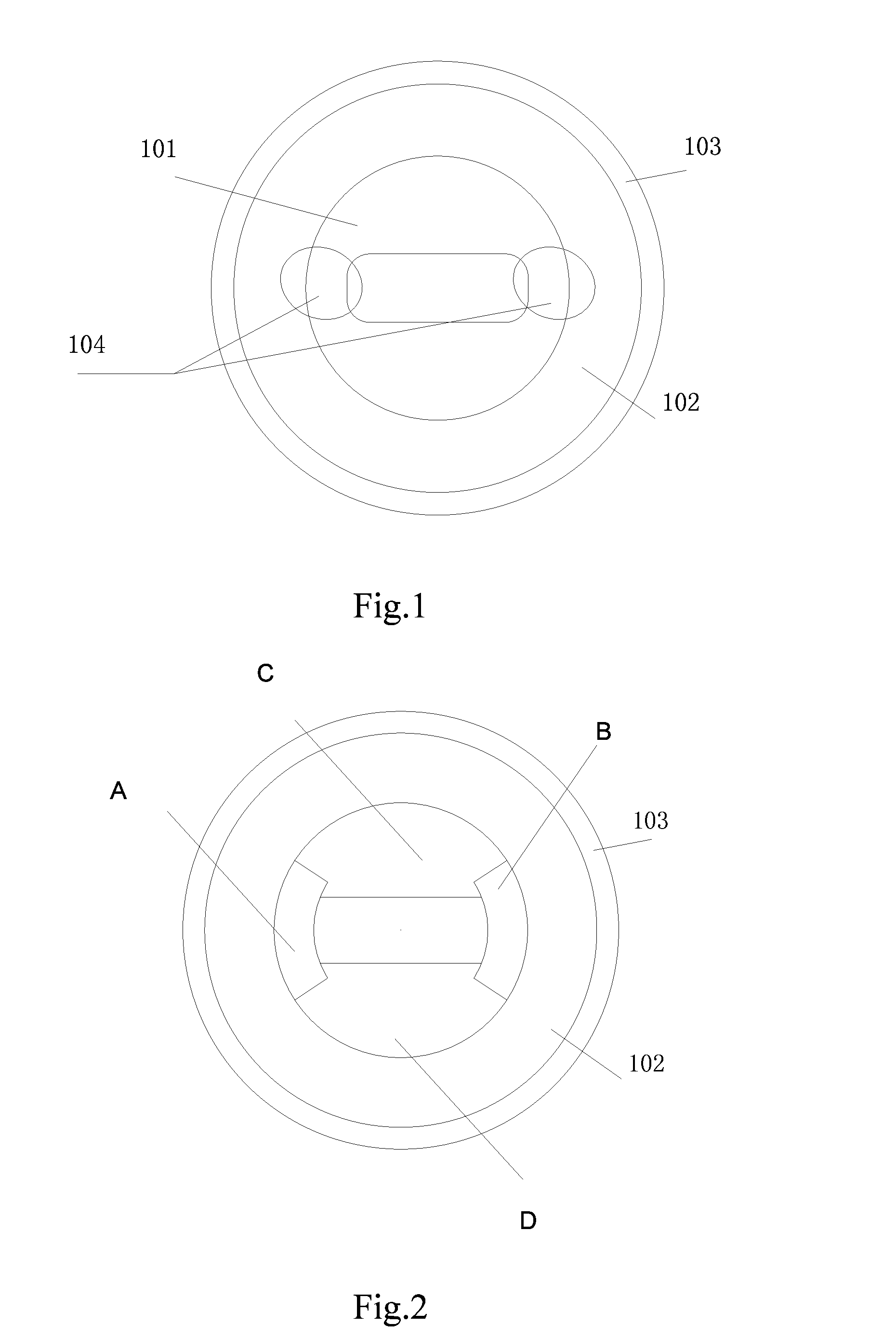
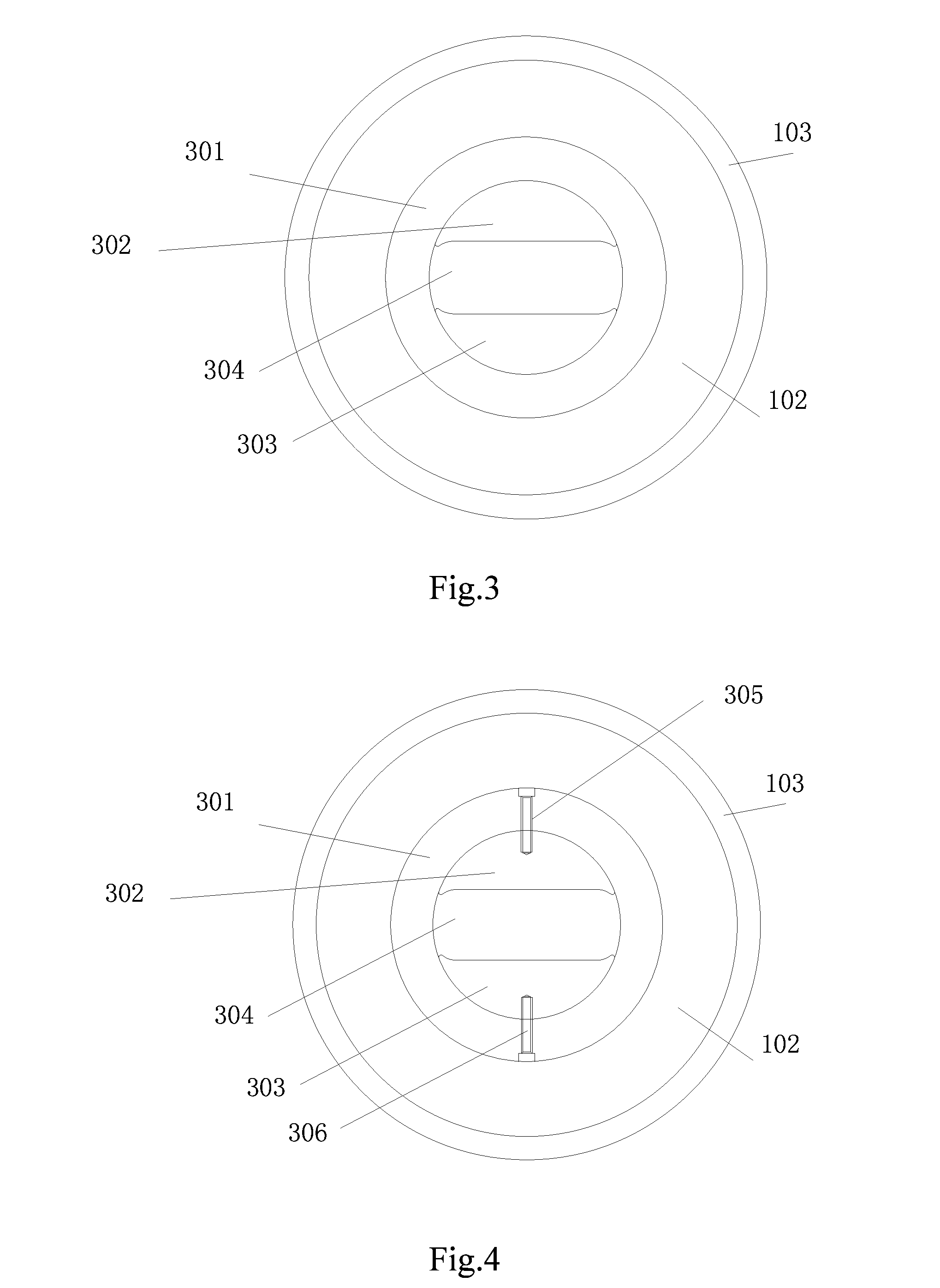
[0031]Referring to FIG. 3, FIG. 3 is a schematic view of an inner sleeve for the flat extrusion cylinder according to the present invention.
[0032]The inner sleeve for the flat extrusion cylinder according to this embodiment of the present invention includes an inner sleeve ring piece 301, upper insert piece 302 and lower insert piece 303.
[0033]The inner sleeve ring piece 302 is positioned in the intermediate sleeve 102 of the flat extrusion cylinder.
[0034]The upper insert piece 302 and lower insert piece 303 are symmetrically located on an inner wall of the inner sleeve ring piece 301, respectively. The upper insert piece 302 and lower insert piece 303 define an inner sleeve working die cavity 304 of the flat extrusion cylinder.
[0035]As shown in FIG. 3, each of the upper insert piece 302 and lower insert piece 303 has a crescent-shaped cross-section. An arc surface of the crescent-shaped cross-section matches with the arc surface of the inner sleeve ring piece 301.
[0036]The upper in...
second embodiment
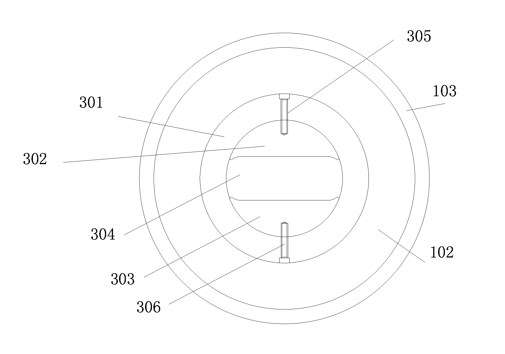
[0038]Referring to FIG. 4, FIG. 4 is a schematic view of an inner sleeve for the flat extrusion cylinder according to the present invention.
[0039]The inner sleeve for the flat extrusion cylinder according to this embodiment further includes at least two countersunk head bolts for fixing the upper insert piece and the lower insert piece on the inner wall of the inner sleeve ring piece.
[0040]As shown in FIG. 4, this embodiment preferably adopts two countersunk head bolts, i.e., an upper countersunk head bolt 305 and a lower countersunk head bolt 306, respectively.
[0041]The upper countersunk head bolt 305 is used to fix the upper insert piece 302 on the inner wall of the inner sleeve ring piece 301.
[0042]The lower countersunk head bolt 306 is used to fix the lower insert piece 303 on the inner wall of the inner sleeve ring piece 301.
[0043]It is noted that, in order to save material and reduce manufacture process in this embodiment, only two countersunk head bolts are used. Of cause, in...
PUM
| Property | Measurement | Unit |
|---|---|---|
| temperature | aaaaa | aaaaa |
| pressure | aaaaa | aaaaa |
| friction | aaaaa | aaaaa |
Abstract
Description
Claims
Application Information
 - R&D
- Intellectual Property
- Life Sciences
- Materials
- Tech Scout
- Unparalleled Data Quality
- Higher Quality Content
- 60% Fewer Hallucinations
Browse by: Latest US Patents, China's latest patents, Technical Efficacy Thesaurus, Application Domain, Technology Topic, Popular Technical Reports.
© 2025 PatSnap. All rights reserved.Legal|Privacy policy|Modern Slavery Act Transparency Statement|Sitemap|About US| Contact US: help@patsnap.com


