Welding torch, welding tip, and welding robot

a welding tip and welding robot technology, applied in the direction of shielding support devices, electrode accessories, manufacturing tools, etc., can solve the problems of poor electrical connection to the welding wire, inconvenient attachment and removal of welding tips having screw mechanisms, and displaced welding positions, etc., to achieve convenient attachment and removal, and simplified operation of attaching

Inactive Publication Date: 2012-05-24
KOBE STEEL LTD
View PDF3 Cites 24 Cited by
  • Summary
  • Abstract
  • Description
  • Claims
  • Application Information

AI Technical Summary

Benefits of technology

[0041]With the welding tip according to the present invention, the welding tip can be easily attached to and removed from the welding torch.
[0042]The welding robot according to the present invention has advantages the same as those of the w

Problems solved by technology

As a result, the inner diameter of the through hole is increased, so that the welding position may be displaced or poor electrical connection to the welding wire may occur.
However, it is inconvenient to attach and remove a welding tip having a screw mechanism.
Moreover, if the thread is stripped, it is impossible to attach and remove the welding tip.
In such a case, the welding efficiency is negatively affected by the time required to remove and attach the welding tip.
Moreover, if tip fusion occurs, it is very difficult to remove a welding tip having a screw mechanism, because it is necessary to twist and cut off the wire.
Here, the term “tip fusion” refers to a problem that occurs when a welding wire has become fused with an inner peripheral surface at the distal end of the welding tip and that causes a failure in feeding of the welding wire.
In addition, a screw mechanism is not suitable for automating the operation of attaching and removing the welding tip, because it is necessary to rotate the welding tip.
In particular, a technology that automates the operation of attaching and removing a welding tip and that solves the problem of tip fusion has not been realized to date.
However, in the mechanism described in Japanese Unexamined Patent Application Publication No. 2005-144548, the welding tip is only inserted

Method used


Image

  • Welding torch, welding tip, and welding robot
  • Welding torch, welding tip, and welding robot
  • Welding torch, welding tip, and welding robot

Examples


examples

[0105]Comparison between a result of welding performed by using a welding torch having the structure according to the present invention (hereinafter referred to as “example”) and a result of welding performed by using an exiting welding torch that do not have the structure according to the present invention (hereinafter referred to as “comparative example”) will be described.

Welding Torch

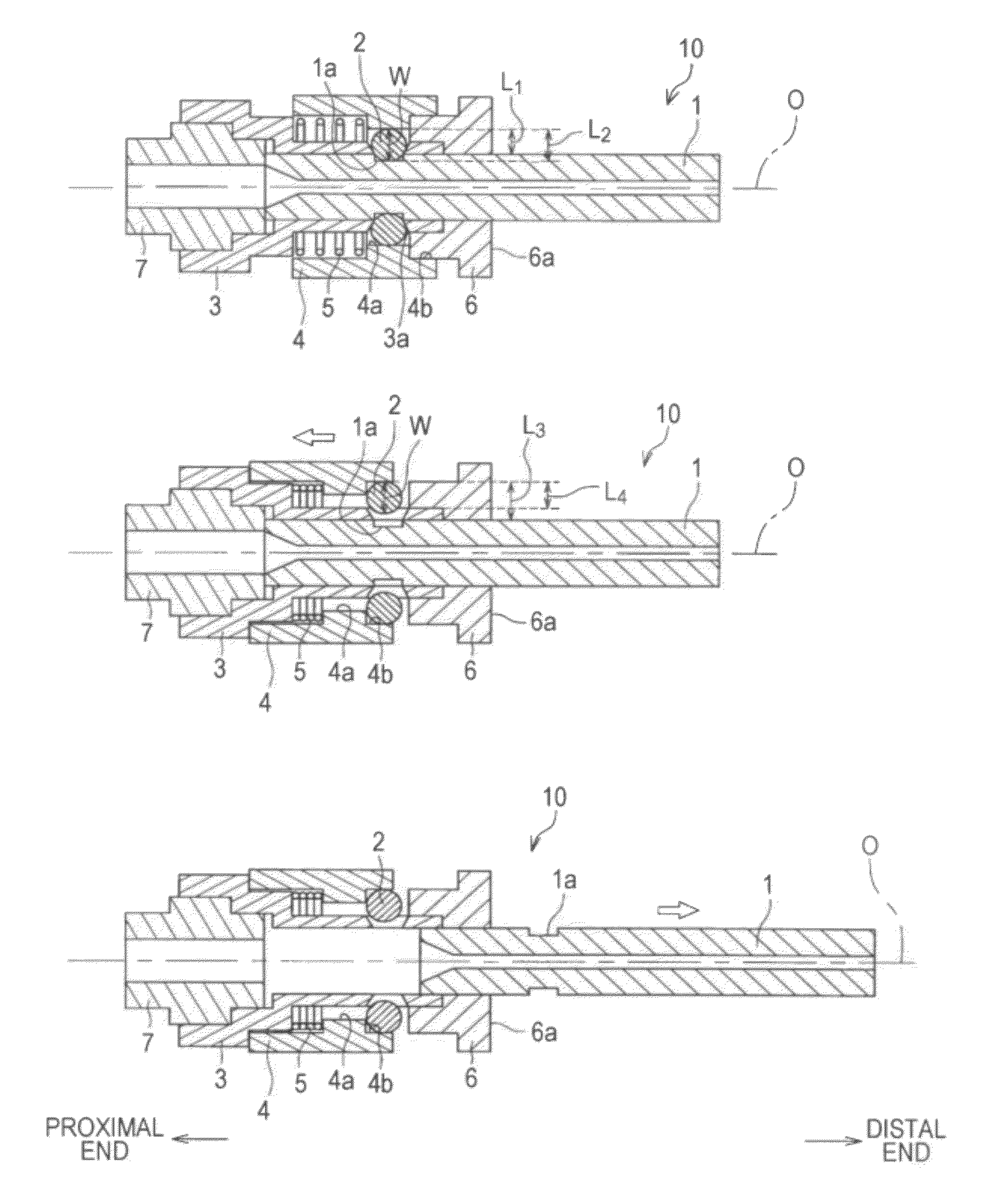
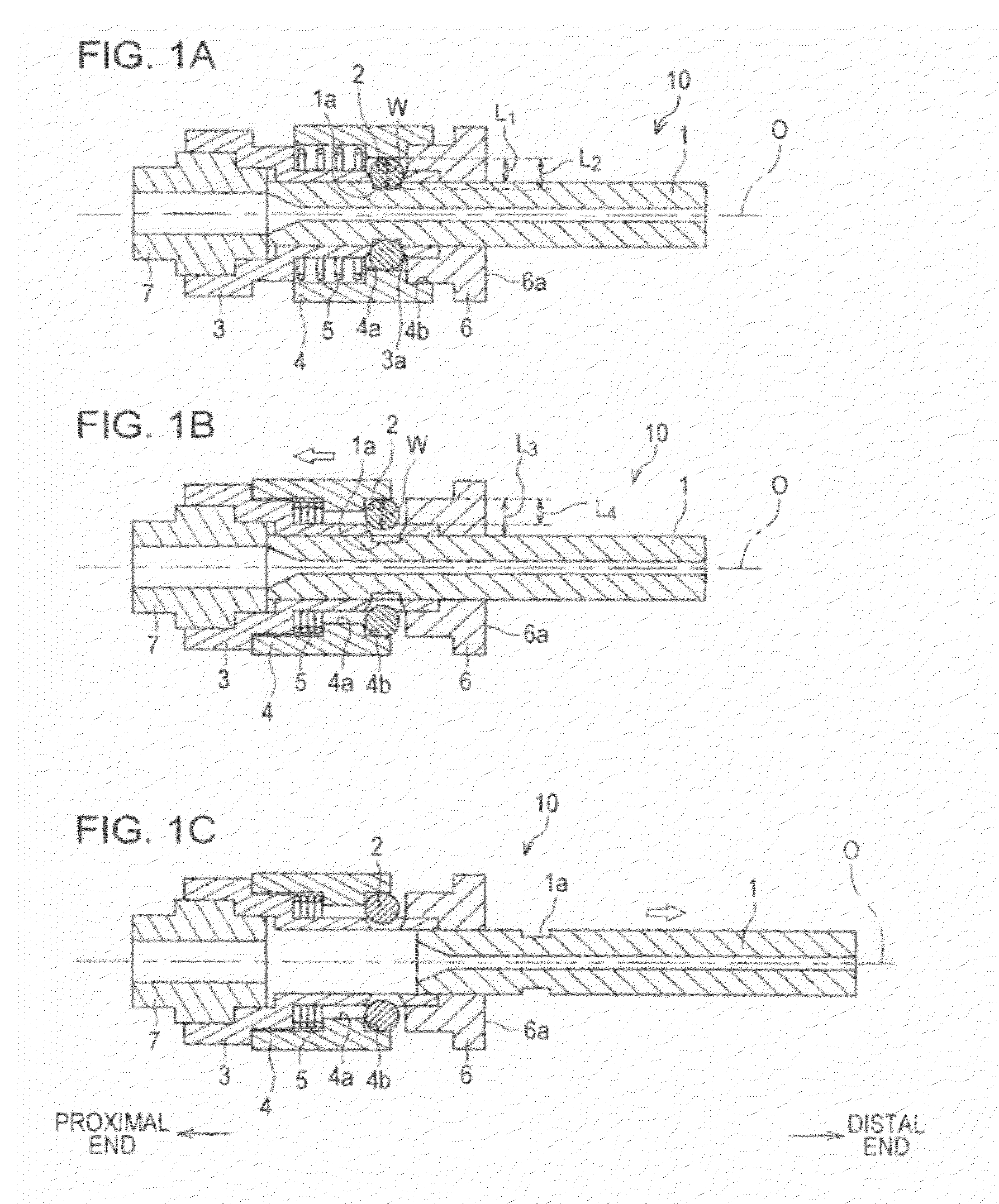
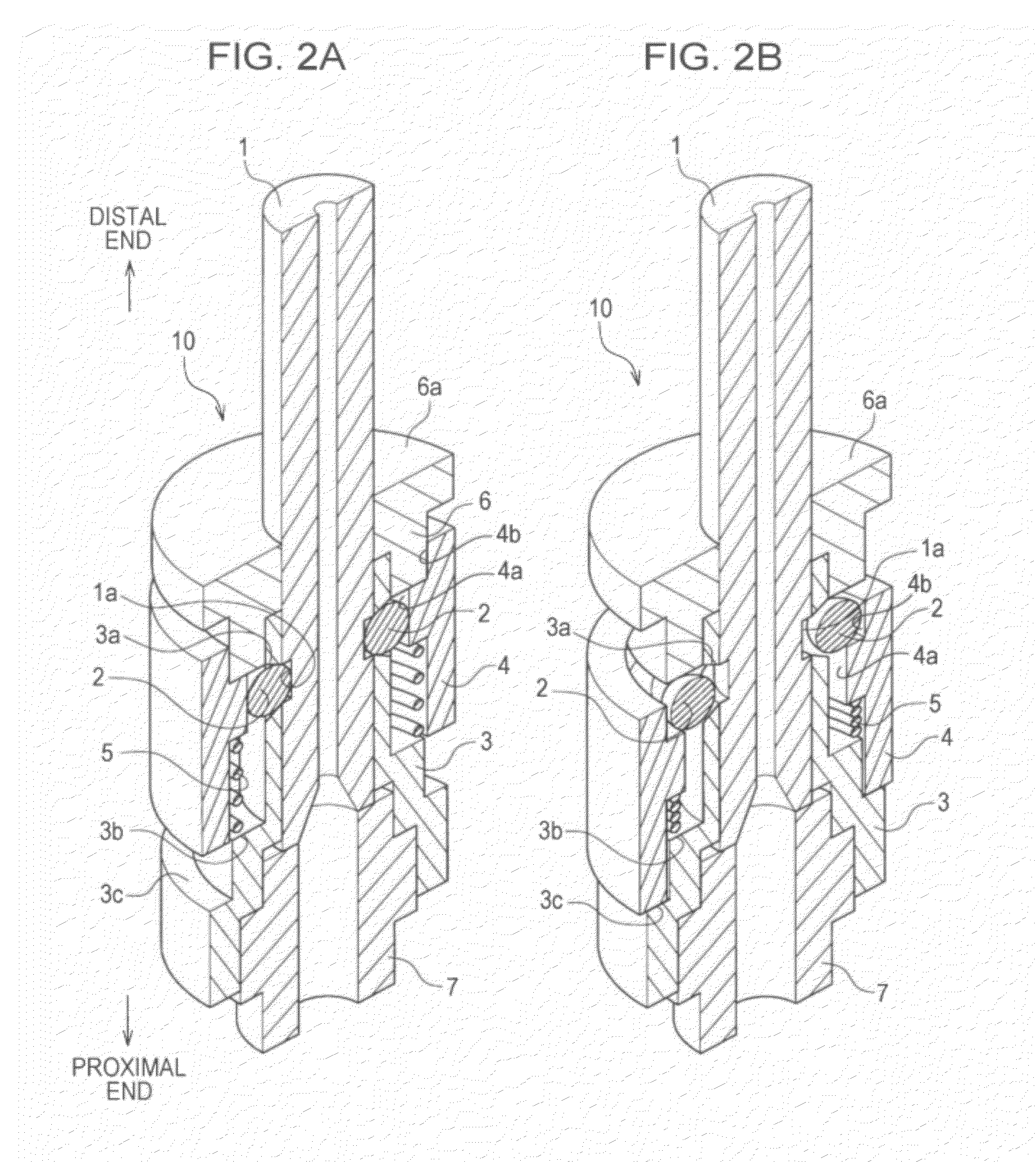
[0106]As illustrated in FIGS. 1A to 1C, a welding torch according to the example includes a welding tip having a fixing groove, a tip connection body having a fixing hole, a holding member including a smaller diameter portion and a larger diameter portion, an elastic member, spherical fixing members, an annular shield member, and a connection member.

[0107]A welding torch according to the comparative example, which is an existing welding torch, includes a welding tip having an external thread on an outer peripheral surface of a proximal end portion, and a tip connection body having an internal thread...


PUM

PropertyMeasurementUnit
Diameteraaaaaaaaaa
Shapeaaaaaaaaaa
Widthaaaaaaaaaa

Abstract

A welding torch includes a tip connection body, a holding member, a fixing member, and a welding tip. The holding member is displaceable in the axial direction of the tip connection. The fixing member fixes the welding tip in place in the axial direction of the welding tip when the fixing member is in contact with a smaller diameter portion, and the fixing member releases the welding tip when the fixing member is in contact with a larger diameter portion.

Description

BACKGROUND OF THE INVENTION[0001]1. Field of the Invention[0002]The present invention relates to a welding torch, a welding tip, and a welding robot that are used for gas-shielded arc welding.[0003]2. Description of the Related Art[0004]In general, a contact tip (hereinafter referred to as a welding tip) is used for gas-shielded arc welding. A welding tip is a consumable copper electrode, and an electric current is supplied to a welding wire through the welding tip. A through hole is formed in the welding tip, and the welding wire is continuously fed into the through hole while an electric current is being supplied to the welding wire through the welding tip, and thereby an arc is generated between a base material and the welding wire that protrudes from the distal end of the welding tip.[0005]When gas-shielded arc welding is performed, the inner peripheral surface of the through hole in the distal end of the welding tip is abraded by the welding wire. As a result, the inner diamete...

Claims


Application Information

Patent Timeline
IPC IPC(8): B23K9/00
CPCB23K9/123B23K9/295B23K9/173B23K9/26B23K9/29
Inventor IZUTANI, SHUNSUZUKI, REIICHI
Owner KOBE STEEL LTD
Why Eureka
Try Eureka