Firearm sight having an ultra high definition video camera

a video camera and sight technology, applied in the field of firearms, can solve the problems of difficult for firearms to achieve a high degree of accuracy in hitting their targets, and achieve the effect of improving the accuracy of the next sho

Active Publication Date: 2012-05-24
RUDICH DAVID
View PDF7 Cites 41 Cited by
  • Summary
  • Abstract
  • Description
  • Claims
  • Application Information

AI Technical Summary

Benefits of technology

[0021]A sighting apparatus for a firearm is capable of firing at least a first and second projectile out of a firearm barrel, the sighting apparatus includes a video camera having a sufficient frame speed rate and resolution to be capable of tracking the path of each projectile when shot from the firearm and capturing a series of images. The series of images include at least a first image taken of a target containing field that is captured at a time before and generally concurrently with the firing of the first projectile, and additional images taken of a target containing field that is captured before and generally concurrently with the projectile reaching the distance of the target, a video display screen is provided for the user to employ to sight the target and aim the firearm. The video display includes a display of an image of the target containing field and a reticle positioned to permit the user to aim the firearm by positioning the reticle over the target. A processor includes an input interface in c

Problems solved by technology

It is often difficult for firearms to achieve a high degree of accuracy in hitting their targets when the firearms solely employ an optical sighting mechanism such as open “iron” sites to a sighting

Method used


Image

  • Firearm sight having an ultra high definition video camera
  • Firearm sight having an ultra high definition video camera
  • Firearm sight having an ultra high definition video camera

Examples


Embodiment Construction

[0041]A. An Overview of the Present Invention.

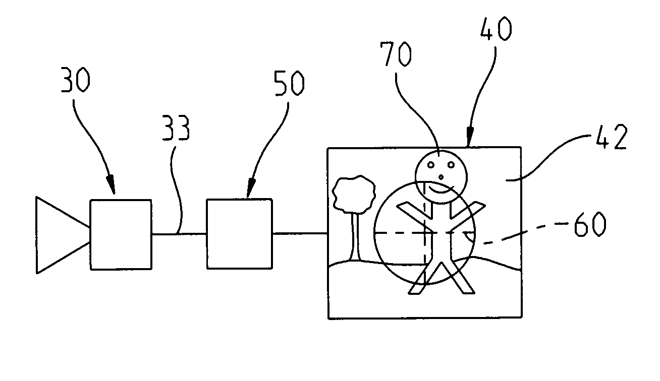
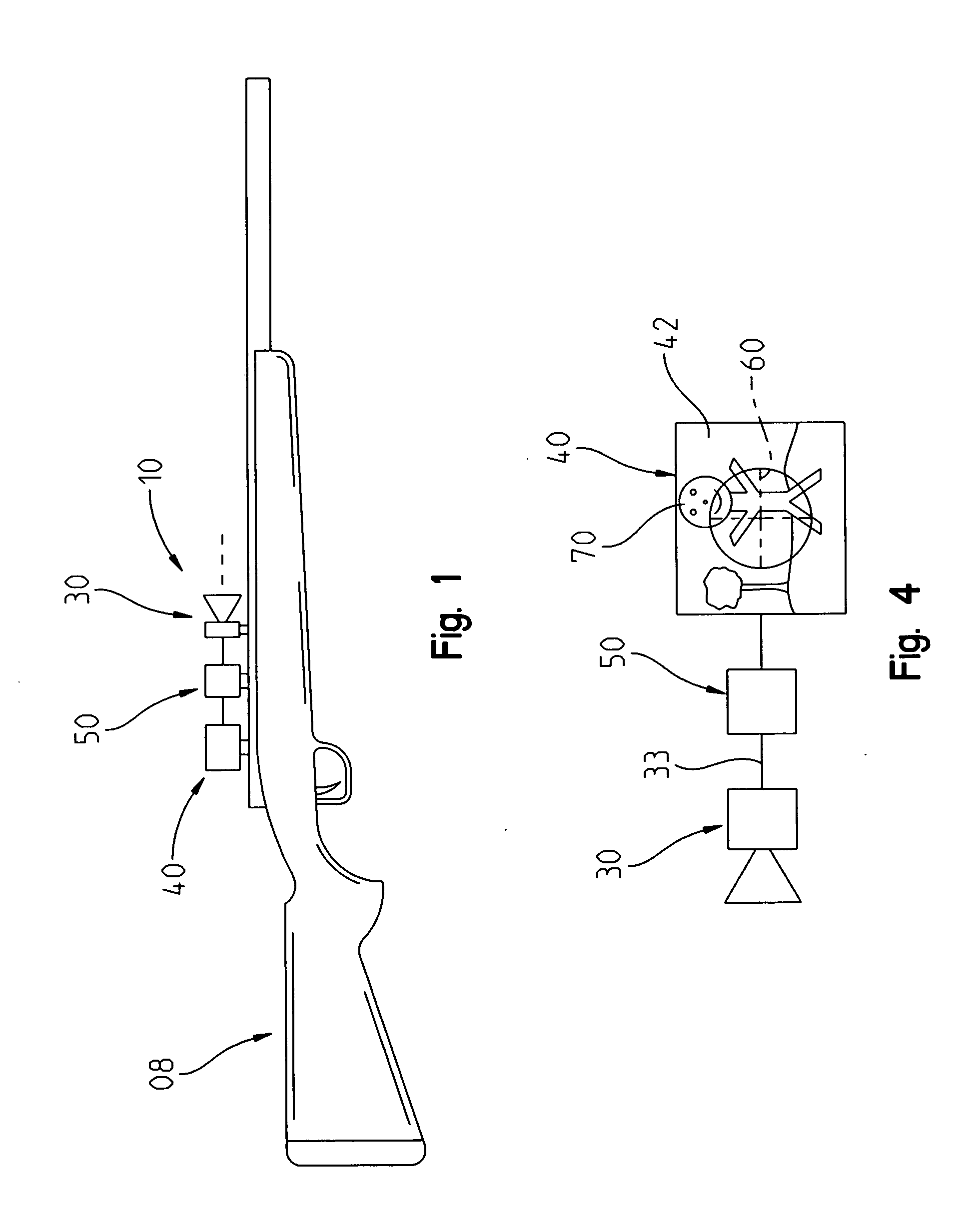
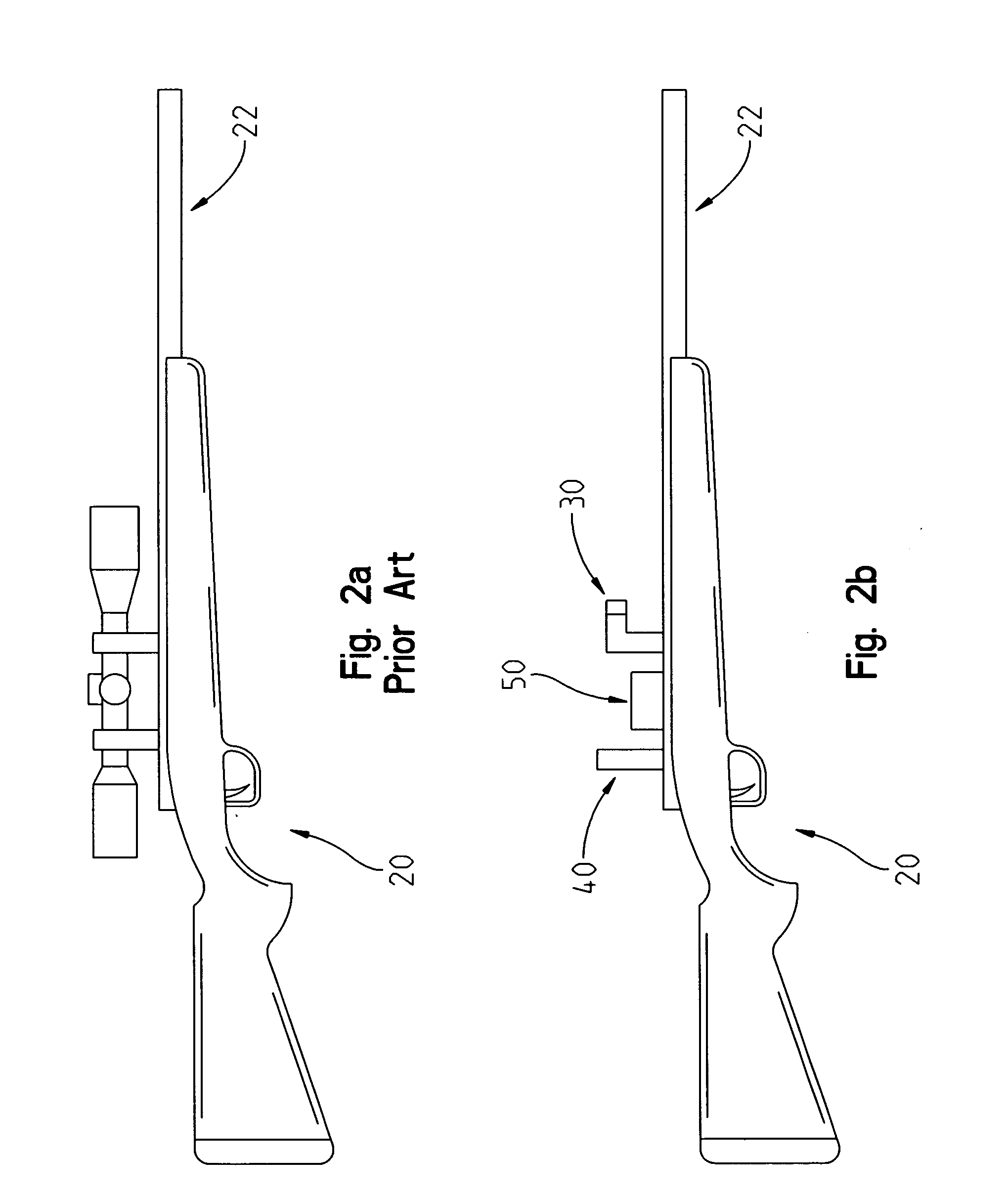
[0042]A sighting mechanism of the present invention is characterized in that a high speed, ultra high definition digital video camera is arranged on the firearm in such a manner that it has a lens capture area disposed parallel to the barrel of the firearm so that the camera can and does capture the target field, the area surrounding the target field, and the flight path of a fired projectile on a video screen. An integrated digital computer unit is in communication with the camera. The computer has a video input interface for receiving digital image data from the video camera. In essence, the integrated digital computer unit comprises a digital image processing computer that allows a selectable image portion of the image data received from the video camera to be superimposed in a pixel precise fashion and in real-time to form a target image and an image of the projectile in flight and to be displayed on the screen

[0043]The digital compu...


PUM


Abstract

A sighting apparatus for a firearm includes a video camera capable of capturing and tracking the path of a projectile The captured images are taken generally concurrently with the firing of the first projectile, and the projectile reaching the the target. A video display includes a reticle positioned at the center of the display to permit the user to aim the firearm by positioning the reticle over the target. A processor receives captured images from the camera. An output interface delivers information to the video display to enable the video display to display images of the target area. Software and a processor determine the flight path of the projectile and the point where the projectile impacts or passes by the intended target and adjusts for the variance between the two points by moving the image on the display.

Description

REFERENCE TO RELATED APPLICATIONS[0001]This application claims the benefit of Rudich, U.S. Provisional Application No. 61 / 415,166, filed 18 Nov. 2010, which application is fully incorporated herein by reference.I. TECHNICAL FIELD OF THE INVENTION[0002]The present invention relates to fire arms, and more particularly, to a firearm system having a sighting mechanism that enables the user to achieve a better target hit rate by enabling the user to correct for such things as distance, weather conditions, windage and gravity.II. BACKGROUND OF THE INVENTION[0003]It is often difficult for firearms to achieve a high degree of accuracy in hitting their targets when the firearms solely employ an optical sighting mechanism such as open “iron” sites to a sighting telescope. This difficulty is caused in particular by various influences having an increasing impact on the ability to accurately aim the rifle, as the distances from the rifle to the target increase. One influence on the inaccuracy of...

Claims


Application Information

Patent Timeline
IPC IPC(8): G06G7/80
CPCF41G11/001F41G1/00F41G3/165F41G3/08F41G3/142F41G3/06F41G1/54
Inventor RUDICH, DAVID
Owner RUDICH DAVID
Why Eureka
Try Eureka