Flat panel display with an integrated touch screen panel

a touch screen panel and display panel technology, applied in the field can solve the problems of reducing the visibility of images, increasing increasing manufacturing costs, so as to reduce the thickness of flat panel displays, reduce the number of substrates, and improve the effect of transmittan

Inactive Publication Date: 2012-05-24
SAMSUNG DISPLAY CO LTD
View PDF6 Cites 60 Cited by
  • Summary
  • Abstract
  • Description
  • Claims
  • Application Information

AI Technical Summary

Benefits of technology

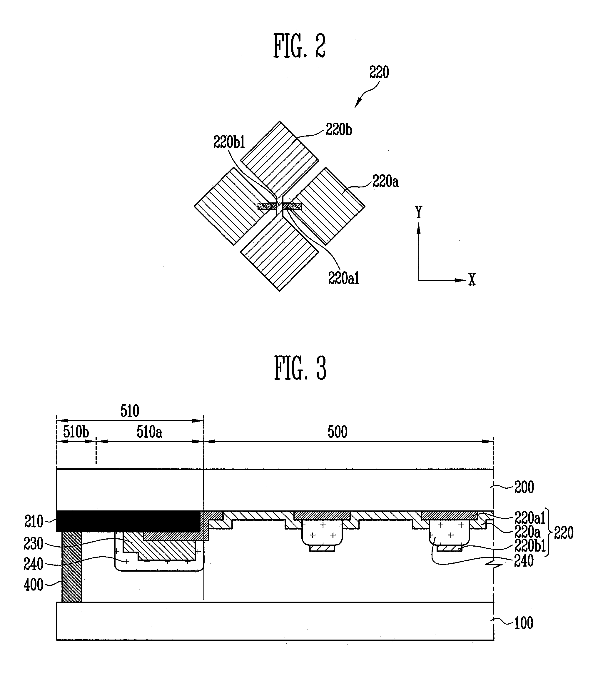
[0022]According to the embodiments of the present invention described above, it is possible to minimize or reduce the thickness of a flat panel display with an integrated touch screen panel and improve transmittance by reducing the number of substrates, by using the upper substrate of the flat panel display as the substrate of the touch screen panel.
[0023]Further, it is possible to improve visibility of an image, and durability and reliability of a touch screen panel by locating sensing patterns of the touch screen panel on the inner side of the upper substrate of the display panel.
[0024]Further, it is possible to simplify the manufacturing process and the unit cost of the product by coupling a touch screen panel and a display panel to one flexible printed circuit board.

Problems solved by technology

However, when a touch screen panel separately manufactured is attached to the outside of the display panel of a flat panel display, the entire thickness of the flat panel display increases, the manufacturing cost also increases, and visibility of an image is reduced by a gap between the touch screen panel and the display panel.
Further, in this case, separate driving ICs for the display panel and the touch screen panel are used, such that compatibility between products may be reduced, and an individual FPCB may be connected with each of the display panel and the touch screen panel, such that the manufacturing process is complicated and the unit cost of a product increases.

Method used


Image

  • Flat panel display with an integrated touch screen panel
  • Flat panel display with an integrated touch screen panel
  • Flat panel display with an integrated touch screen panel

Examples


Embodiment Construction

[0033]In the following detailed description, only certain exemplary embodiments of the present invention have been shown and described, simply by way of illustration. As those skilled in the art would realize, the described embodiments may be modified in various different ways, all without departing from the spirit or scope of the present invention. Accordingly, the drawings and description are to be regarded as illustrative in nature and not restrictive. In addition, when an element is referred to as being “on” another element, it can be directly on the another element or be indirectly on the another element with one or more intervening elements interposed therebetween. Also, when an element is referred to as being “connected to” or “coupled to” another element, it can be directly connected to the another element or be indirectly connected to the another element with one or more intervening elements interposed therebetween. Hereinafter, like reference numerals refer to like element...


PUM


Abstract

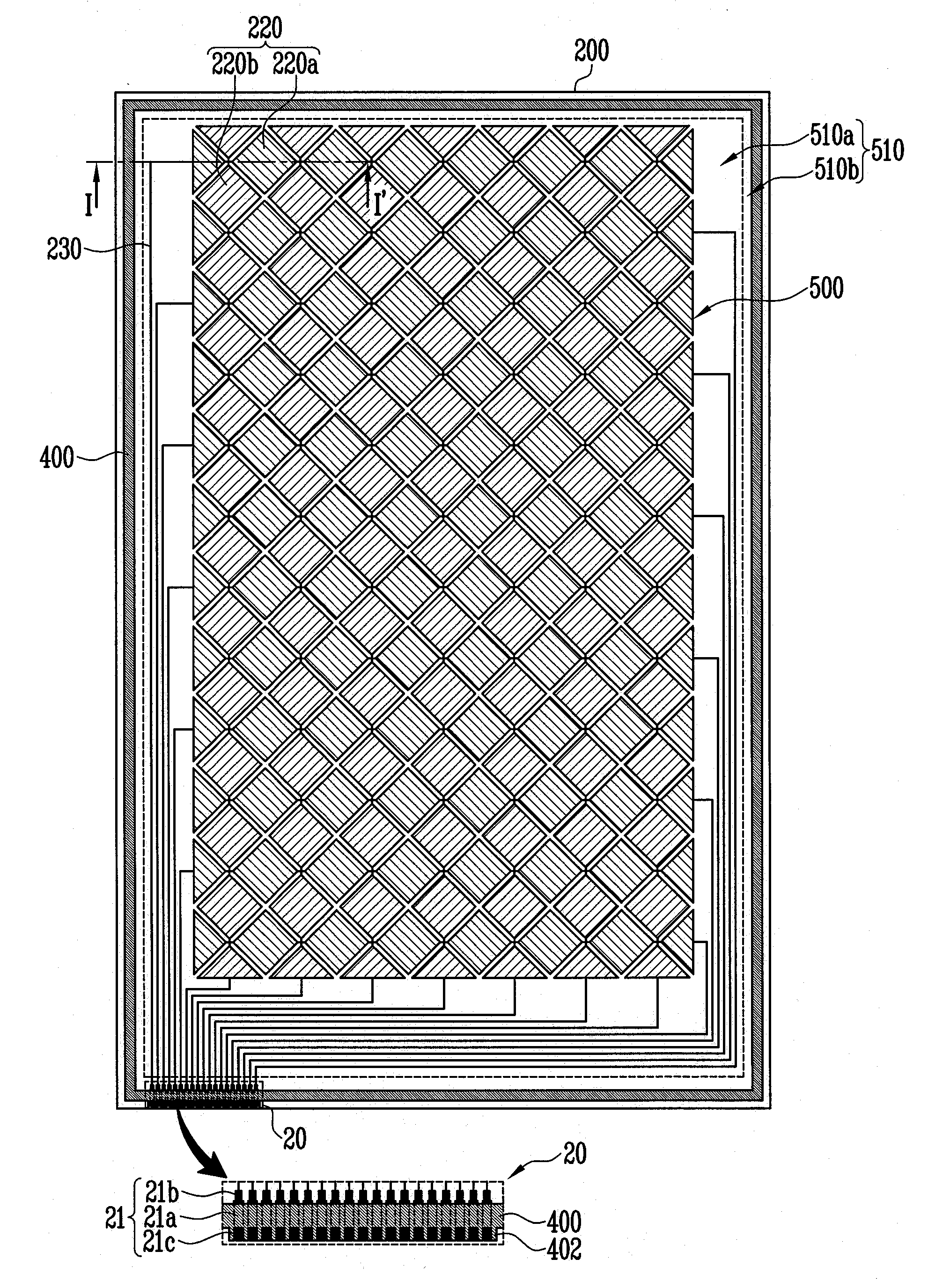
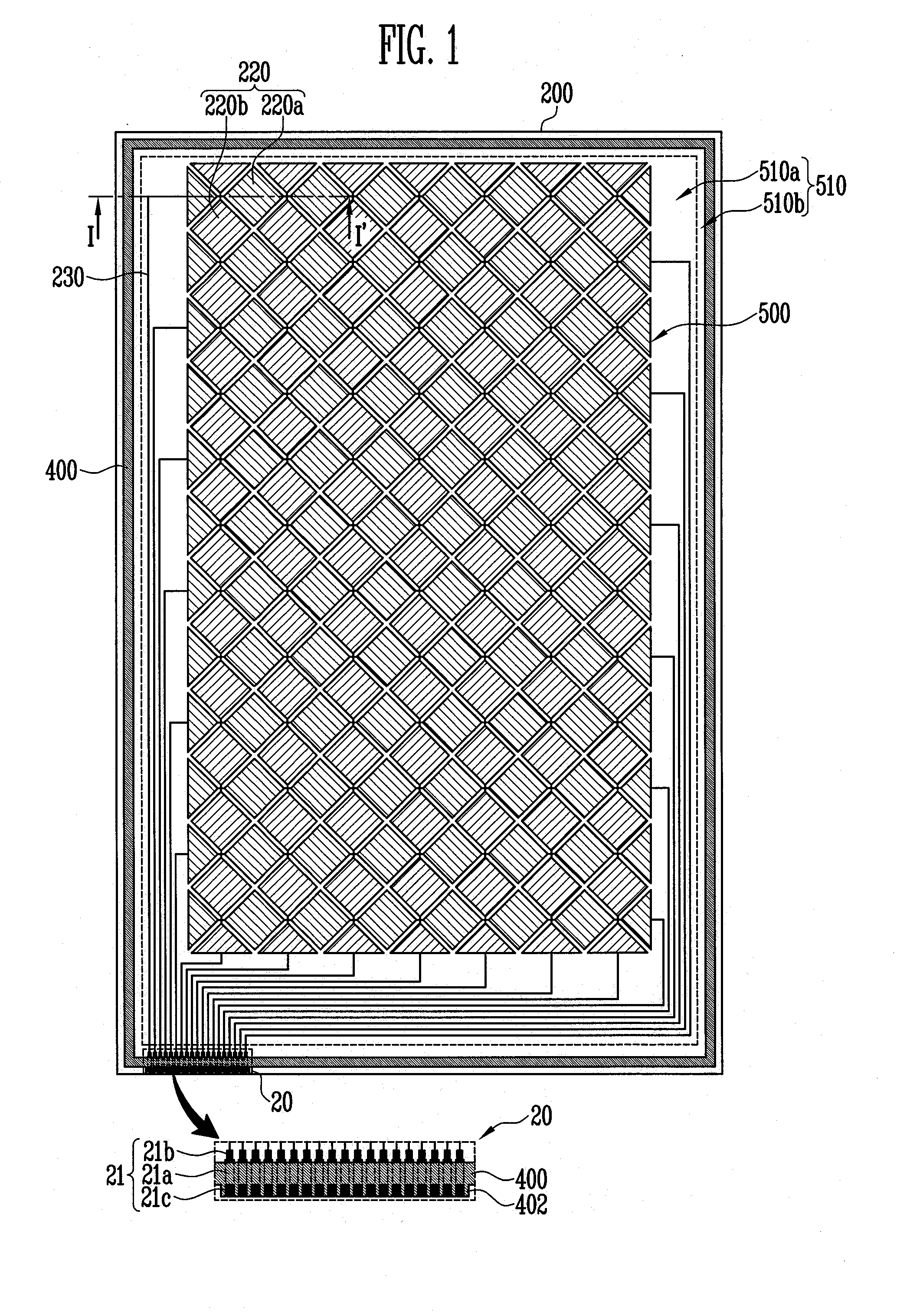
A flat panel display with an integrated touch screen panel according to an embodiment of the present invention includes: an upper substrate and a lower substrate; a plurality of sensing patterns in a display region of the upper substrate facing the lower substrate; a plurality of sensing lines coupled with the sensing patterns, respectively, in a first non-display region of the upper substrate; a sensing pad unit including a plurality of sensing pads coupled with the sensing lines, at a second non-display region of the upper substrate; a sealant between the upper substrate and a second non-display region of the lower substrate; seal patterns protruding from and perpendicular to the sealant in a region overlapping the sensing pads, the seal patterns being between the sensing pads; and a plurality of metal patterns at the second non-display region of the lower substrate overlapping the regions between the seal patterns.

Description

CROSS-REFERENCE TO RELATED APPLICATION[0001]This application claims priority to and the benefit of Korean Patent Application No. 10-2010-0116851, filed on Nov. 23, 2010, in the Korean Intellectual Property Office, the entire content of which is incorporated herein by reference.BACKGROUND[0002]1. Field[0003]Aspects of embodiments according to the present invention relate to a flat panel display, particularly, a flat panel display with an integrated touch screen panel.[0004]2. Description of Related Art[0005]Touch screen panels are input devices that can be used to select contents displayed on the screen of an image display device, etc., with a person's hand or an object to input commands of a user.[0006]To this end, the touch screen panels are provided on a front face of the image display device and convert positions where a person's hand or an object directly contacts into electrical signals. Accordingly, the instruction selected at the contact point is received as an input signal.[...

Claims


Application Information

Patent Timeline
Patent Type & Authority Applications(United States)
IPC IPC(8): G06F3/041
CPCG06F3/044G06F3/0446G02F1/13338G06F3/0412G06F2203/04111G06F2203/04103G06F3/0416
Inventor JUN, WOO-SIK
Owner SAMSUNG DISPLAY CO LTD
Why Eureka
Try Eureka