Organic Light Emitting Display Device

a display device and light-emitting technology, applied in the direction of basic electric elements, semiconductor devices, electrical equipment, etc., can solve the problems of inability to maintain the mechanical strength of the mask, difficulty in applying the fmm to a large-area or high-resolution display device, etc., to achieve the effect of reducing the gap between the openings of the fmm, high resolution and large area

Active Publication Date: 2021-07-01
LG DISPLAY CO LTD
View PDF8 Cites 1 Cited by
  • Summary
  • Abstract
  • Description
  • Claims
  • Application Information

AI Technical Summary

Benefits of technology

[0005]As for a conventional organic light emitting display device, a fine metal mask (FMM) is used when an organic emission layer is formed in each sub-pixel. However, it is difficult to apply the FMM to a large-area or high-resolution display device due to a fabrication tolerance, sagging and a shadow effect of the mask. Particularly, as demands for large area and high resolution increase, the gap between openings of the FMM needs to be reduced. During a manufacturing process of the organic light emitting display device, the openings may be clogged by an organic material or metals defining the openings may stick together. Also, a mechanical strength of the mask may not be maintained.

Problems solved by technology

However, it is difficult to apply the FMM to a large-area or high-resolution display device due to a fabrication tolerance, sagging and a shadow effect of the mask.
During a manufacturing process of the organic light emitting display device, the openings may be clogged by an organic material or metals defining the openings may stick together.
Also, a mechanical strength of the mask may not be maintained.

Method used


Image

  • Organic Light Emitting Display Device
  • Organic Light Emitting Display Device
  • Organic Light Emitting Display Device

Examples


Embodiment Construction

[0029]Advantages and characteristics of the present disclosure and a method of achieving the advantages and characteristics will be clear by referring to exemplary embodiments described below in detail together with the accompanying drawings. However, the present disclosure is not limited to the exemplary embodiments disclosed herein but will be implemented in various forms. The exemplary embodiments are provided by way of example only so that those skilled in the art can fully understand the disclosures of the present disclosure and the scope of the present disclosure. Therefore, the present disclosure will be defined only by the scope of the appended claims.

[0030]The shapes, sizes, ratios, angles, numbers, and the like illustrated in the accompanying drawings for describing the exemplary embodiments of the present disclosure are merely examples, and the present disclosure is not limited thereto. Like reference numerals generally denote like elements throughout the specification. F...


PUM

PropertyMeasurementUnit
emission areasaaaaaaaaaa
axis lengthaaaaaaaaaa
lengthaaaaaaaaaa

Abstract

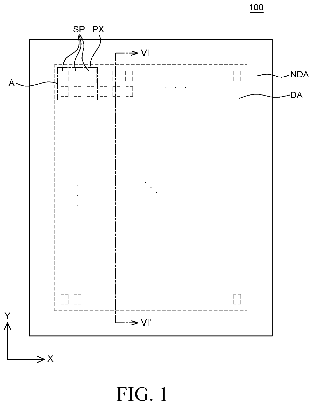
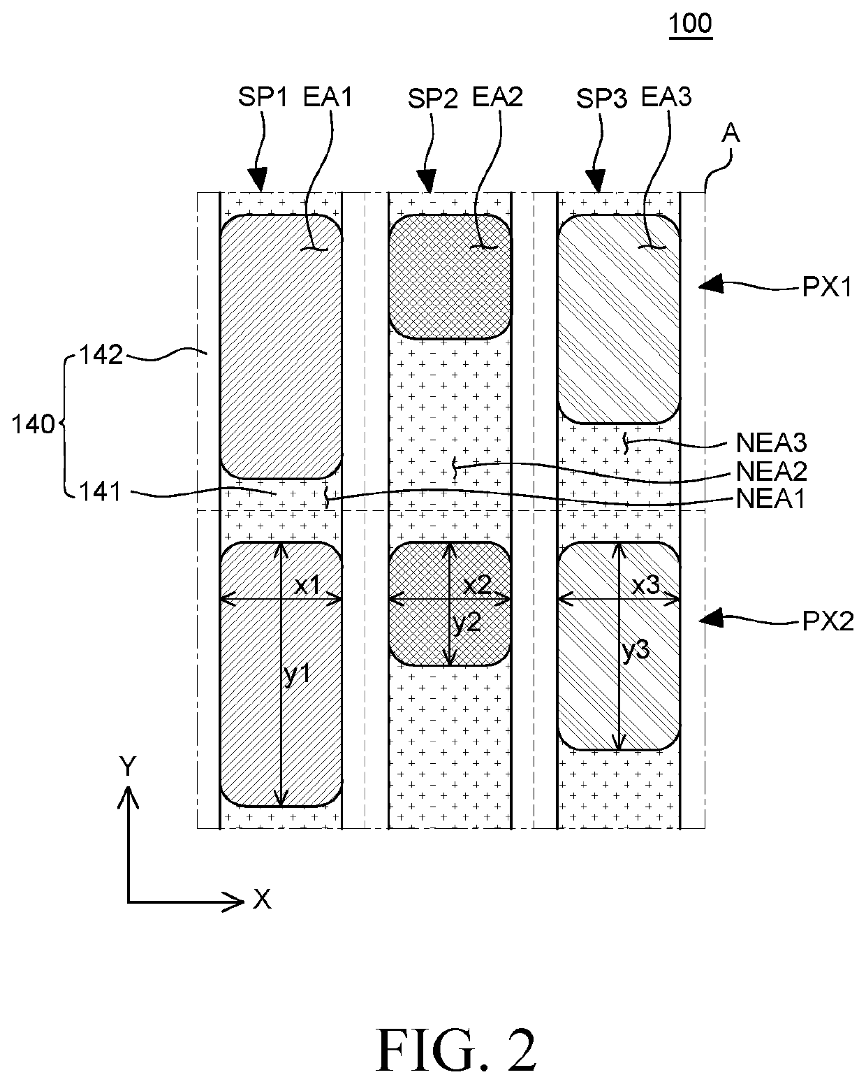
Provided is an organic light emitting display device. The organic light emitting display device includes a plurality of sub-pixels, an anode disposed in each of the plurality of sub-pixels, a bank layer covering an edge of the anode and defining emission areas, an organic emission layer disposed on the anode, and a cathode disposed on the organic emission layer. Each of sub-pixels includes a respective one of the emission areas and a respective non-emission area. A minor axis length of the emission area in the first sub-pixel, that of the emission area in the second sub-pixel and that of the emission area in the third sub-pixel are identical to each other. A major axis length of the emission area in the first sub-pixel, that of the emission area in the second sub-pixel and that of the emission area in the third sub-pixel are different from each other.

Description

CROSS-REFERENCE TO RELATED APPLICATIONS[0001]This application claims the priority of Republic of Korea Patent Application No. 10-2019-0179896 filed on Dec. 31, 2019 with the Korean Intellectual Property Office, the disclosure of which is incorporated herein by reference.BACKGROUNDField[0002]The present disclosure relates to an organic light emitting display device and more particularly, to an organic light emitting display device which is improved in display quality by reducing color mixing of inks and thickness deviation of an organic emission layer when the organic emission layer is formed through a solution process.Description of Related Art[0003]As the information age advances, the field of a display device for visually displaying electrical information signals has grown rapidly. Accordingly, various studies on display devices are ongoing to improve the performance such as thinning, weight lightening, and low power consumption.[0004]Among various display devices, an organic ligh...

Claims


Application Information

Patent Timeline
Patent Type & Authority Applications(United States)
IPC IPC(8): H01L27/32H01L51/52
CPCH01L27/3218H01L27/3246H01L51/5228H01L51/5212H01L27/3276H10K59/35H10K59/353H10K59/12H10K59/131H10K59/352H10K59/122H10K59/123H10K50/814H10K50/824H10K50/80
Inventor LEE, HAKMINKIM, HEEJIN
Owner LG DISPLAY CO LTD
Why Eureka
Try Eureka