
Device and procedure for implanting a dental implant

a technology for dental implants and devices, applied in dental surgery, dental tools, medical science, etc., can solve the problems of adding additional stress to implants, burdening patients, and difficult to place trephine drills in such a manner as to maintain desired positions, so as to improve cutting accuracy, improve control over tools, and improve the effect of tool control

Inactive Publication Date: 2012-05-24
NOBEL BIOCARE SERVICES AG
View PDF8 Cites 18 Cited by
  • Summary
  • Abstract
  • Description
  • Claims
  • Application Information

AI Technical Summary

Benefits of technology

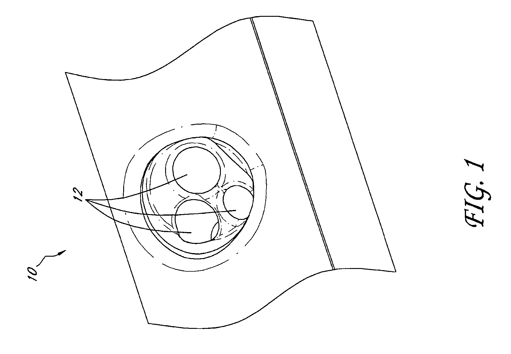
[0011]Further, according to at least one of the embodiments disclosed herein is the realization that in preparing a target site to receive a dental implant, a central area or core of the target site may be used not only to anchor a straight implant, thereby eliminating the need to use an angled abutment and implant in order to correct the angle of an implant placed in a tooth socket, but can also provide valuable autogenous bone material that can be grafted into selected portions or cavities of the target site. In addition, the implant can be used at target sites such as, for example, where the bone height is lower. Bone height can be lower, for example, as a result of regression of the bone, or along the mandible or elsewhere where there is a low bridge ridge.
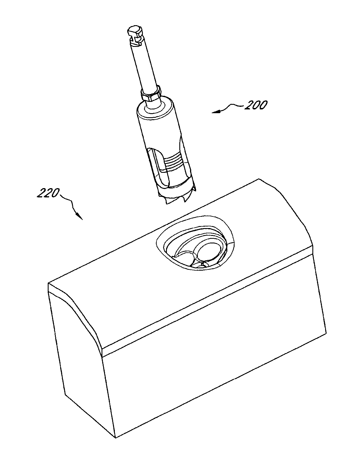
[0034]In another embodiment, a combination is provided for performing an implantation of an implant at a target site. The combination can comprise a guide sleeve and an interradicular burr. The guide sleeve can define inner and outer diameters. The guide sleeve can also comprise a limit flange at a proximal end thereof. Further, the guide sleeve can define an effective longitudinal length. The interradicular burr can define an outer diameter that is less than the inner diameter of the guide sleeve such that the burr can be removably received within the guide sleeve. Additionally, the burr can define an operational longitudinal length that is less than the effective longitudinal length of the guide sleeve. The burr can comprise a corresponding limit flange configured to contact the limit flange of the guide sleeve when the burr is inserted into the guide sleeve. The corresponding limit flange of the burr can be configured to limit the longitudinal movement of the burr within the guide sleeve.

Problems solved by technology

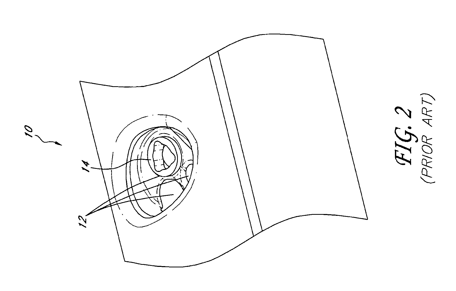
As a result, the final restoration 16 may be misaligned with respect to adjacent teeth and is cantilevered on the implant potentially adding additional stresses to the implant.
However, allowing the site to heal can take up to several months which can be a burden on the patient.
Without the use of the guide tool, it can be particularly difficult to place the trephine drill in such a manner as to maintain a desired position and trajectory of the drill.
During use, the trephine drill can sometimes be very unstable and wobble when it contacts the gum tissue and / or the bone.
Further, in other embodiments, the flange can extend radially outwardly from the tool such that the flange limits the travel of the tool via interference.

Method used


Image

  • Device and procedure for implanting a dental implant
  • Device and procedure for implanting a dental implant
  • Device and procedure for implanting a dental implant

Examples


Embodiment Construction

[0076]While the present description sets forth specific details of various embodiments, it will be appreciated that the description is illustrative only and should not be construed in any way as limiting. Furthermore, various applications of such embodiments and modifications thereto, which may occur to those who are skilled in the art, are also encompassed by the general concepts described herein.

[0077]As discussed above, previous implantation procedures have various disadvantages. For example, when a tooth is extracted and replaced with an implant, a surgeon would have to utilize existing tooth sockets in order to perform such a procedure within a short time frame. Unfortunately, in order to perform such a procedure, an implant would require that an angled abutment be used in addition to the implant in order to compensate for the off-axis geometries of the tooth sockets. As noted above, the use of an angled abutment results in an off-center final restoration. In another example, a...


PUM


Abstract

Various tools and procedures are provided for implantation of an implant at a target site. The procedure can comprise performing an osteotomy at the target site; placing a guide sleeve into the osteotomy; inserting a coring tool into the guide sleeve; coring the target site up to a depth less than the depth of the osteotomy, the coring tool being configured to collect autogenous bone material from the target site during the coring of the target site; placing the implant at the implant site; and grafting the autogenous bone material into selected portions of the target site.

Description

FIELD OF THE INVENTIONS[0001]The present inventions relate generally to dental implant systems and methods of using the same. More specifically, the present inventions relate to methods and apparatuses for implant placement procedures and systems.DESCRIPTION OF THE RELATED ART[0002]Implant dentistry involves the restoration of one or more teeth in a patient's mouth using artificial components. Such artificial components typically include a dental implant and a prosthetic tooth and / or a final abutment that is secured to the dental implant.[0003]The dental implant is implanted into the alveolar bone (i.e., jawbone) of a patient. Typically, the surgeon first accesses the alveolar bone through the patient's gum tissue and removes any remains of the tooth to be replaced. Next, the specific site in the alveolar bone where the implant will be anchored is prepared by drilling and / or reaming to accommodate the width of the dental implant to be inserted. Then, the dental implant is inserted i...

Claims


Application Information

Patent Timeline
IPC IPC(8): A61C8/00A61C19/04A61C3/02
CPCA61C8/0089A61C1/084
Inventor NOURIAM, PEDRAMHURSON, STEVEN M.
Owner NOBEL BIOCARE SERVICES AG
Learn More