Lower Limb Prosthesis

Active Publication Date: 2012-05-24
BLATCHFORD PRODS
View PDF7 Cites 51 Cited by
  • Summary
  • Abstract
  • Description
  • Claims
  • Application Information

AI Technical Summary

Benefits of technology

[0012]The ankle joint mechanism defines an ankle joint flexion range extending from a dorsi-flexion limit to a plantar-flexion limit. Typically, these flexion limits are, respectively, between 2° and 5° and between 5° and 8° with respect to a mid-stance condition of the ankle joint mechanism. Between these dorsi- and plantar-flexion limits, the ankle joint mechanism is substantially inelastic in the sense that it is not resiliently biased. Consequently, over significant portions of the gait cycle, reaction moments about the ankle are largely dissipated with the result that voluntary control and proprioception by the amputee is improved. The applicants have found that such an ank

Problems solved by technology

However, such a device is often uncomfortable for the user whilst standing and whilst walking on ramps and stairs and walking at different speeds.
Users have also experienced knee instability and difficulty in maintaining forward motion during roll-over of the foot while standing and walking on ramps and stairs

Method used


Image

  • Lower Limb Prosthesis
  • Lower Limb Prosthesis
  • Lower Limb Prosthesis

Examples


Embodiment Construction

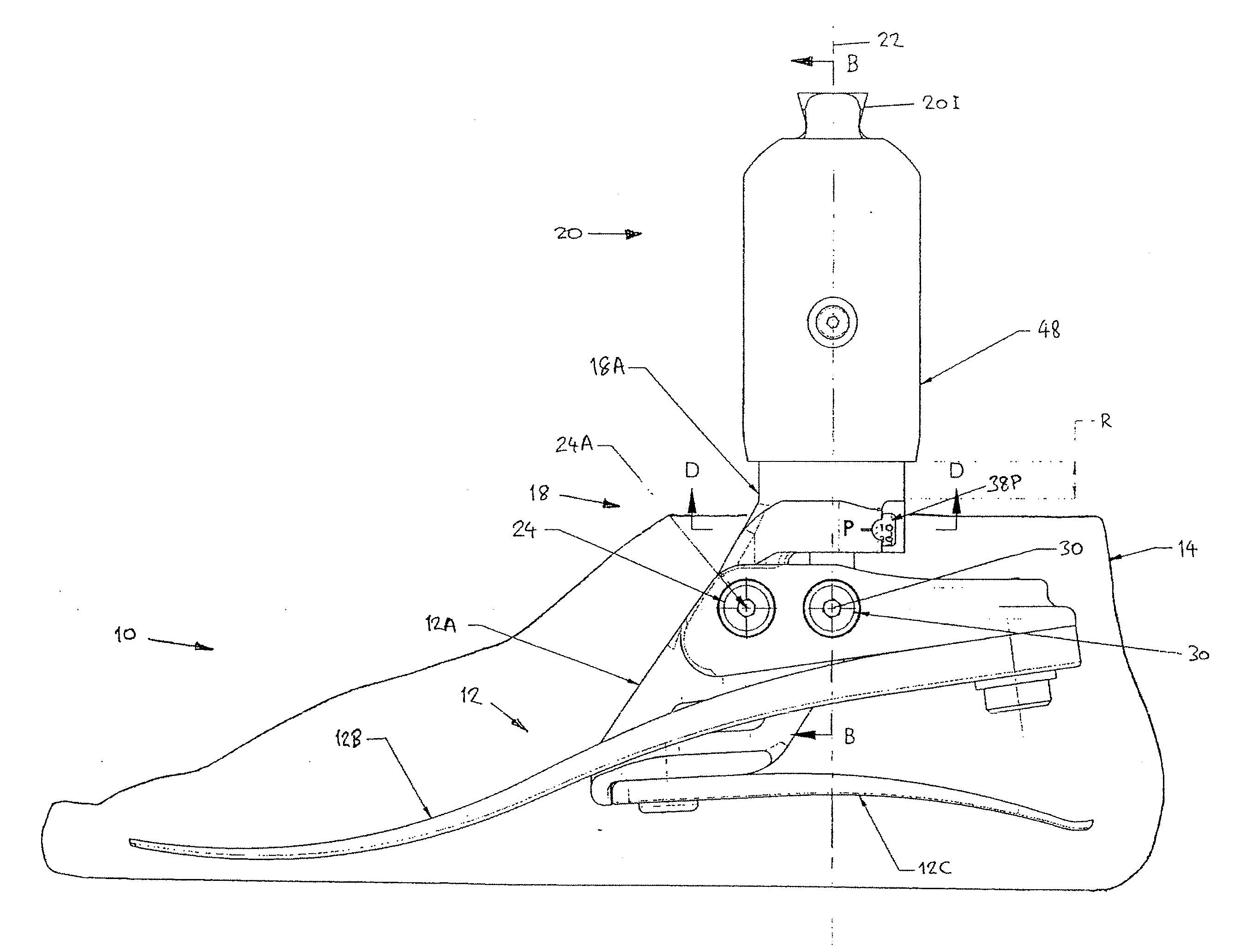
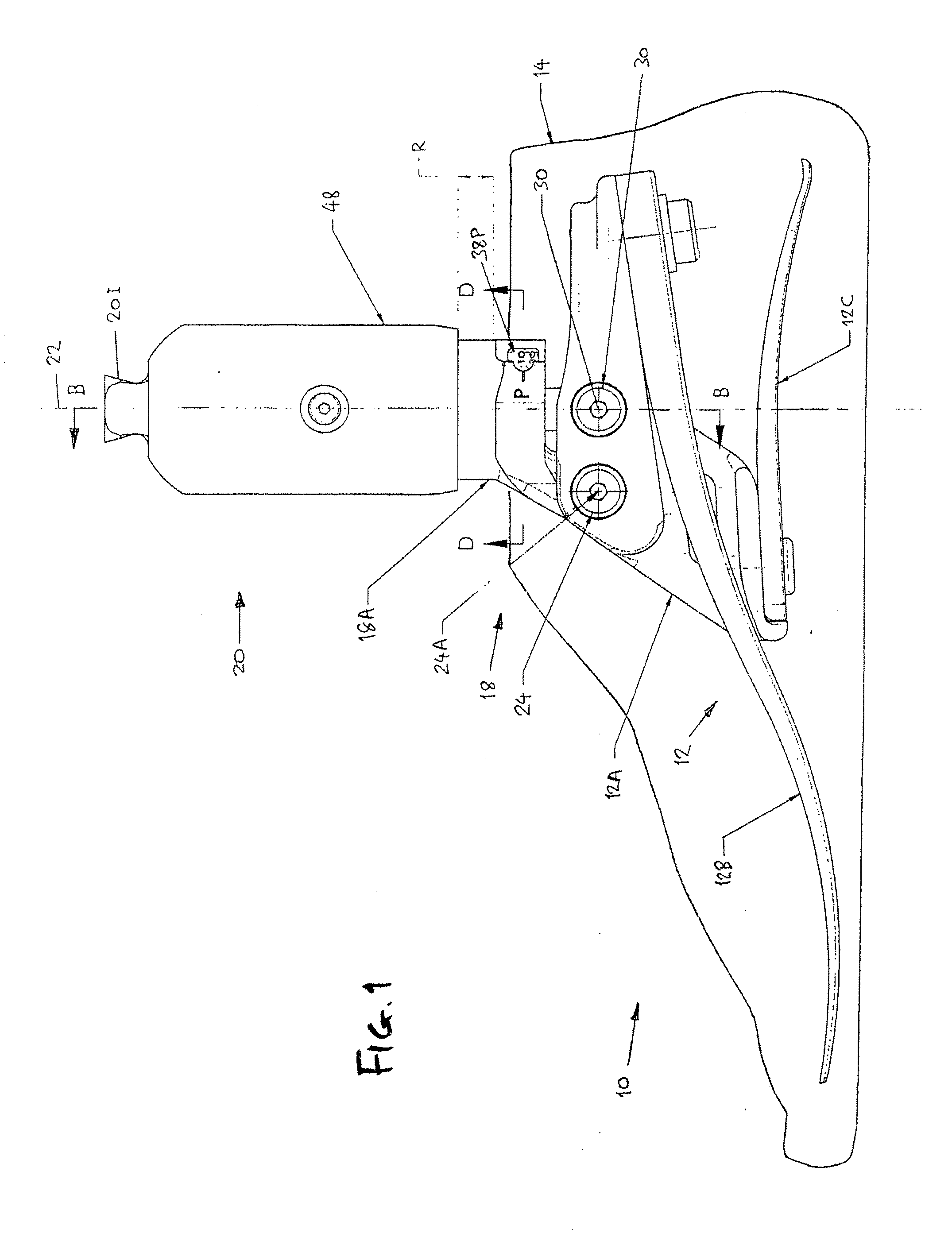
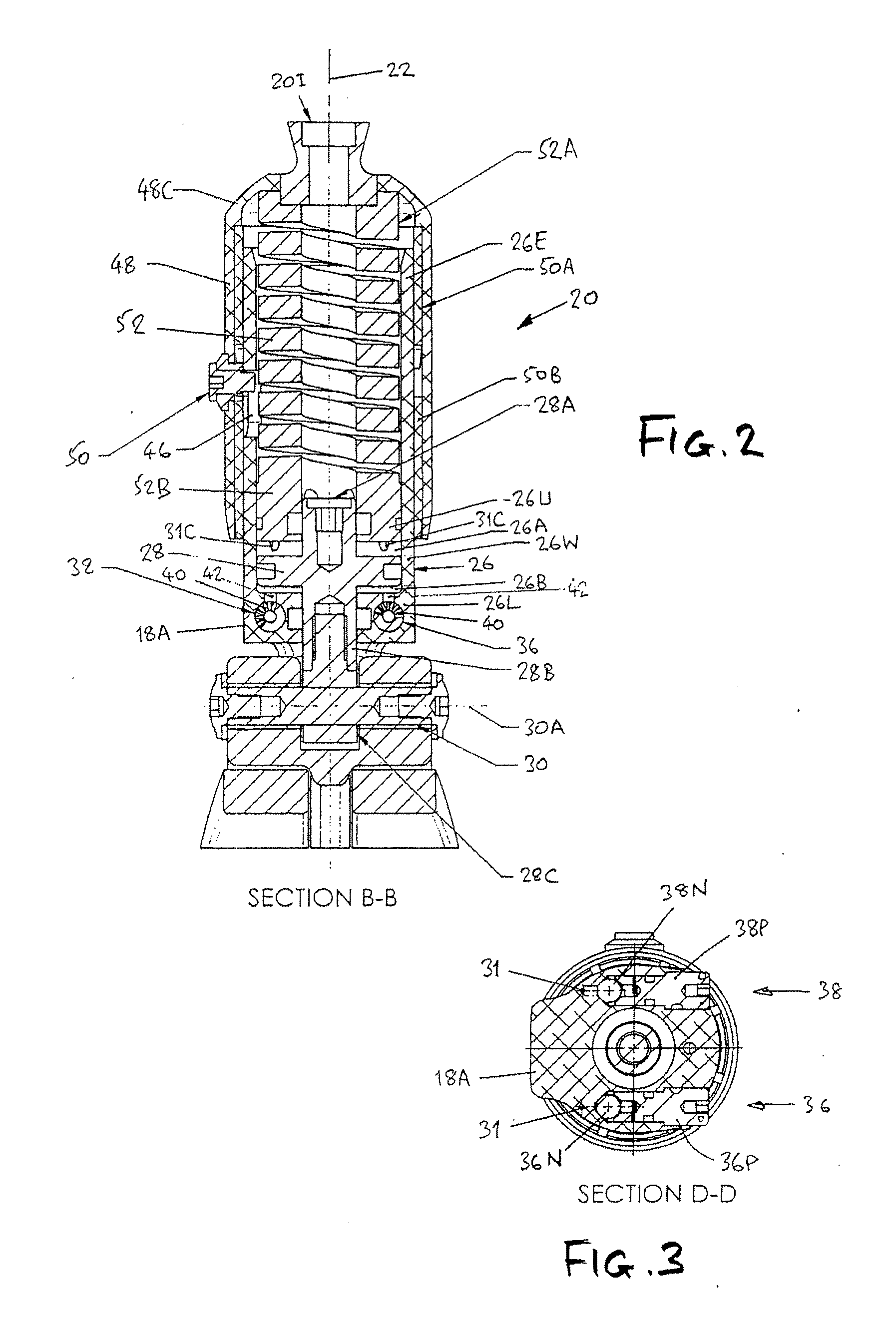
[0008]According to a first aspect of this invention, a lower limb prosthesis comprises a shin component defining a shin axis, a foot component, and an ankle joint mechanism coupling the shin component to the foot component, wherein the ankle joint mechanism provides a continuously hydraulically damped range of ankle flexion and is constructed and arranged such that, over at least part of the range, the damping resistance is the predominant resistance to flexion, and wherein the shin component has a superior part and an inferior part which are resiliently interconnected so as to be translationally displaceable relative to each other according to the axial compressive load on the shin component, the direction of relative displacement being substantially vertical when the foot component is at rest in an unloaded state on a horizontal supporting surface. The mechanism can comprise an hydraulic linear piston and cylinder assembly. The piston may have distal connection means for pivotal c...


PUM


Abstract

In a lower limb prosthesis an ankle unit has a combination of an hydraulic piston and cylinder assembly providing a continuously damped range of ankle flexion and a resilient telescopic shock absorber. The damping resistance of the piston and cylinder assembly is the predominant resistance to ankle flexion and is provided by a piston which is axially moveable in a cylinder centred on the shin axis. The wall of the cylinder has a cylindrical outer bearing surface for a sleeve which is translationally displaceable relative to the piston and cylinder assembly according to the axial load, the sleeve being resiliently mounted by a compression spring which extends axially within the sleeve and has an integral end portion forming an upper bulkhead of the cylinder. The sleeve is also rotatable on the cylinder wall, the spring providing torsional resistance.

Description

CROSS-REFERENCE TO RELATED APPLICATIONS[0001]This application is a continuation-in-part of currently pending U.S. patent application Ser. No. 11 / 956,391, filed Dec. 14, 2007. The present application also claims priority from U.S. Provisional Patent Application No. 61 / 454,060, filed Mar. 18, 2011. The entire contents of the ‘391 and ‘060 applications are expressly incorporated herein by reference.FIELD OF THE INVENTION[0002]This invention relates to a lower limb prosthesis comprising a shin component, a foot component, and an ankle joint mechanism interconnecting the shin and foot components. The ankle joint mechanism is arranged to allow limited damped pivoting movement of the shin component relative to the foot component. The invention also includes a prosthetic ankle unit.BACKGROUND OF THE INVENTION[0003]Current prosthetic foot and ankle systems are generally aligned for operation as fixed mechanical structures comprising elastic and deformable elements designed to provide stabili...

Claims


Application Information

Patent Timeline
IPC IPC(8): A61F2/68
CPCA61F2/6607A61F2/68A61F2002/5006A61F2002/5033A61F2002/6621A61F2002/748A61F2002/6657A61F2002/6854A61F2002/705A61F2002/707A61F2002/745A61F2002/6642A61F2/74A61F2/748
Inventor HARRIS, GRAHAMMOSER, DAVIDZAHEDI, MIR SAEED
Owner BLATCHFORD PRODS
Why Eureka
Try Eureka