Eureka AIR delivers breakthrough ideas for toughest innovation challenges, trusted by R&D personnel around the world.

Methods and systems for desiccant air conditioning

a desiccant air conditioner and desiccant technology, applied in the field of desiccant air conditioning, can solve the problems of air conditioning being the largest operating cost in a building, the humidity level is too low for comfort, and the electricity grid is not working normally

Inactive Publication Date: 2012-05-31
EMERSON CLIMATE TECH INC
View PDF14 Cites 69 Cited by
  • Summary
  • Abstract
  • Description
  • Claims
  • Application Information

AI Technical Summary

Benefits of technology

[0023]In accordance with one or more embodiments, multiple sets of wavy plate structures can be arranged into a stack that has a scalable nature wherein the drying or wetting capacity of the desiccant can easily be expanded by simply adding additional wavy plates.
[0049]In accordance with one or more embodiments, fuel combustion takes place in such a way that the effluent gasses are directed through a set of plate structures having a liquid desiccant on its surfaces. The effluent gasses contain substances such as Carbon Dioxide, Water Vapor and contaminants such as SOx and NOx, which can be captured into the desiccant. In some embodiments, the desiccant is regenerated into a concentrated desiccant and liquid water. In some embodiments, the desiccant is filtered in such a way as to remove acidity created by the SOx and NOx and other gasses absorbed from the fuel combustion process.

Problems solved by technology

It is well known that air conditioning is an enormous source of energy use and that summer cooling in particular can lead to electricity grid problems.
Air conditioning is often the largest operating cost in a building.
In many buildings, such sensible only heating results in humidity levels that are too low for comfort.
Such humidification however results in the cooling of the air, which means that additional heating will have to be applied to counteract the cooling effect of the humidifier.
However, the heating effect that occurs when air is dehumidified in an adiabatic fashion (no heat is added or removed) requires large amounts of sensible cooling post-dehumidification and as a result limits the energy savings that can be obtained.
However, the use of low pressure vacuum systems significantly increases the cost and complexity of the equipment and increases the requirements for maintenance.
Also, each transition (from air to a heat transfer fluid to the desiccant) utilizes heat exchangers, fans, and pumps and thus results in higher costs.
And importantly, such transitions result in larger temperature requirements since each transition is not perfectly efficient.
As a result, absorption chillers require higher temperatures to operate making them less suitable for integration with systems that employ waste heat or low grade heat.
Liquid desiccant systems however have traditionally suffered from the risk of desiccant carry-over into the air stream resulting in sometimes severe corrosion problems in the building since the desiccants that are used are typically strongly corrosive to metals.
The spraying increases the risk of desiccant carryover into the air stream.
However, these mist eliminators require frequent maintenance and replacement.
Furthermore, the process of using a filter media is inherently energy inefficient.
The filter media is an obstruction in the air flow and thus generally requires large fan power.
Also, the filter media typically are thermally non-conductive which makes the dehumidification process adiabatic resulting in undesirable heating of the air.
Increasing the flow rate of course increases the risk of desiccant carry over and requires more liquid pump power.
Furthermore, the drain pans do not easily allow the system to be set up as a “split” system wherein the conditioner and regenerator are located in physically separate locations.
In addition, the drain pans do not easily allow for the system to be expandable: one has to increase the size of the pan—which means a new design, rather than adding capacity through a scalable design.
However this approach still utilizes a horizontal air flow—which makes it much harder to integrate to a rooftop installation—and a very complex conditioner design that has a desiccant drain pan at the bottom, but does not allow for a counter flow between the air and the liquids.
This system also still has the risk of desiccant carryover since the desiccant is still directly exposed to the air flow.
Higher regeneration temperatures necessitate higher quality (temperature) heat sources and thus are less easily available.
At worst, the system has to be powered by a non-waste heat source such as a hot water furnace.
Yazaki absorption units have been powered by evacuated tube solar thermal modules that are able to generate heat as high as 100° C. Concentrated solar thermal modules are able to achieve even higher temperatures, but oftentimes do so at higher costs.
Glazed flat plate solar thermal collectors typically operate at somewhat lower temperatures of 70-80° C., but also lose a significant portion of their efficiency at higher temperature, which means that the array size needs to be increased to generate adequate power.
Unglazed flat plate solar thermal collectors have higher efficiencies at lower temperatures, but generally lose a lot of their efficiency at high temperatures and are usually not able to achieve temperatures higher than 60° C., making them unsuitable for integration with absorption chillers.
None of the solar heat sources mentioned above (concentrated solar thermal, evacuated tube collectors and glazed and unglazed flat plate collectors) generates electricity at the same time as generating heat.
However, all air conditioning systems still require electricity for fans and liquid pumps.
Electricity is oftentimes much more expensive per unit of energy than fuels used for heat.
It is known that solar Photo-Voltaic Modules (PV modules) heat up significantly in direct sun exposure with temperatures approaching 70-80° C. Such temperatures have a deteriorating effect on the performance of the module since module performance degrades with an increase in temperature.
From a cost perspective, solar thermal systems augmented with conventional PV modules are less cost effective than PVT modules and take up more space than PVT modules.
However, PVT modules generally supply lower temperatures and efficiencies than pure solar thermal systems.

Method used


Image

  • Methods and systems for desiccant air conditioning
  • Methods and systems for desiccant air conditioning
  • Methods and systems for desiccant air conditioning

Examples


Embodiment Construction

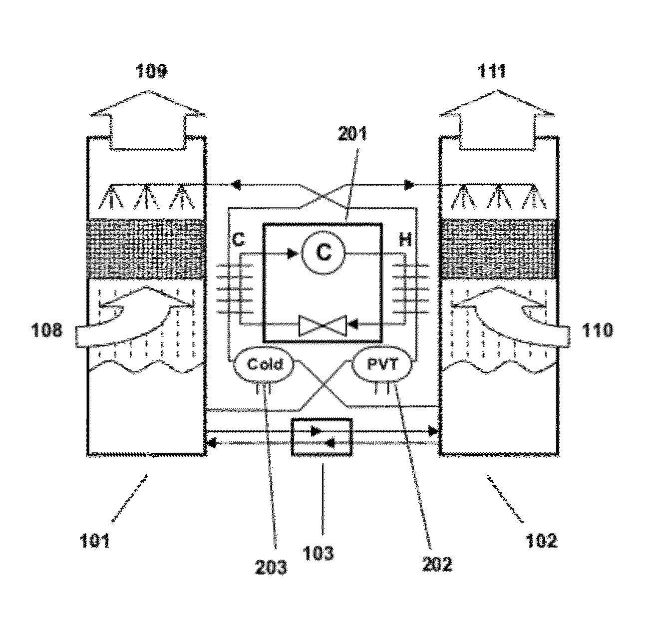
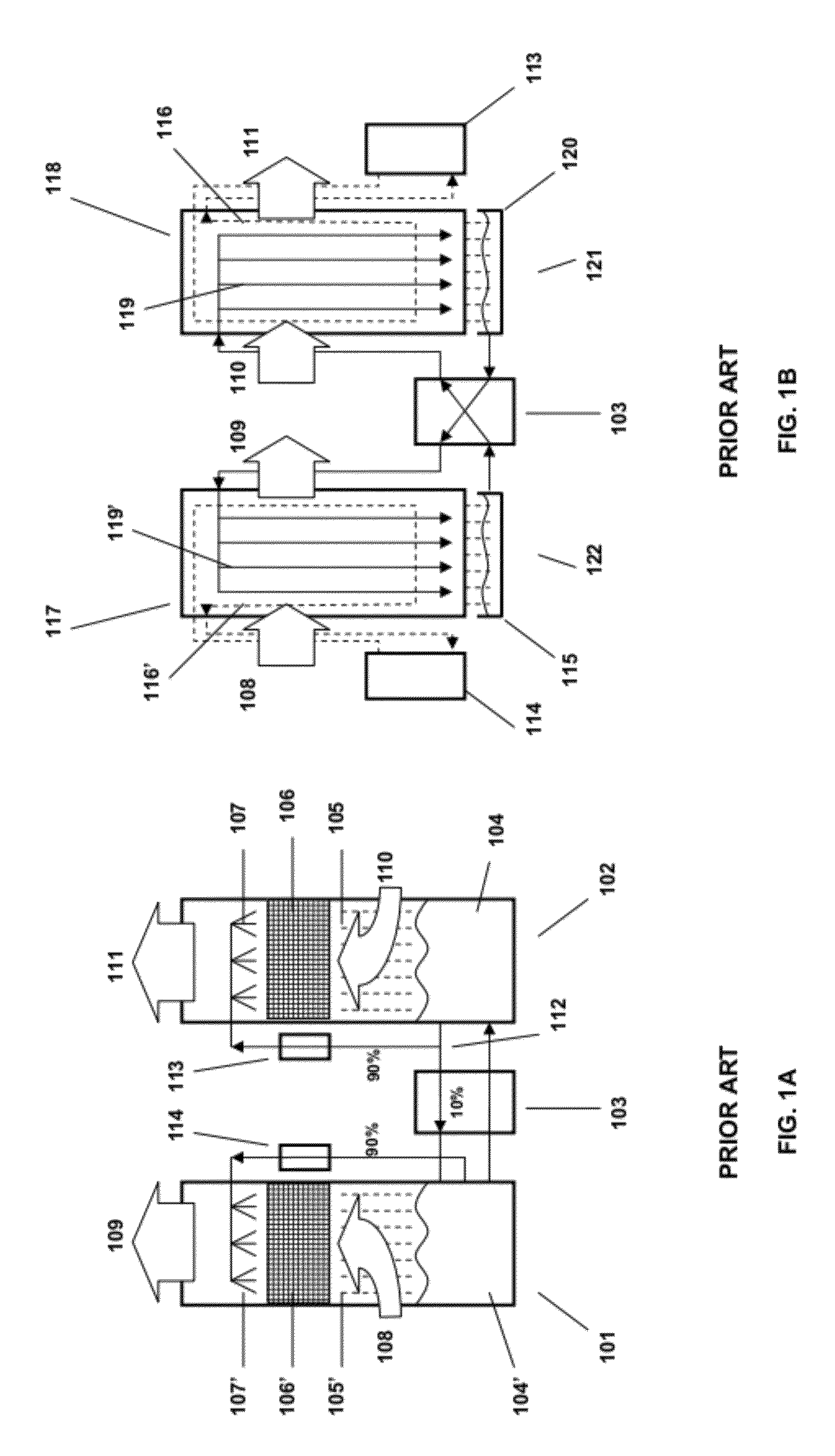
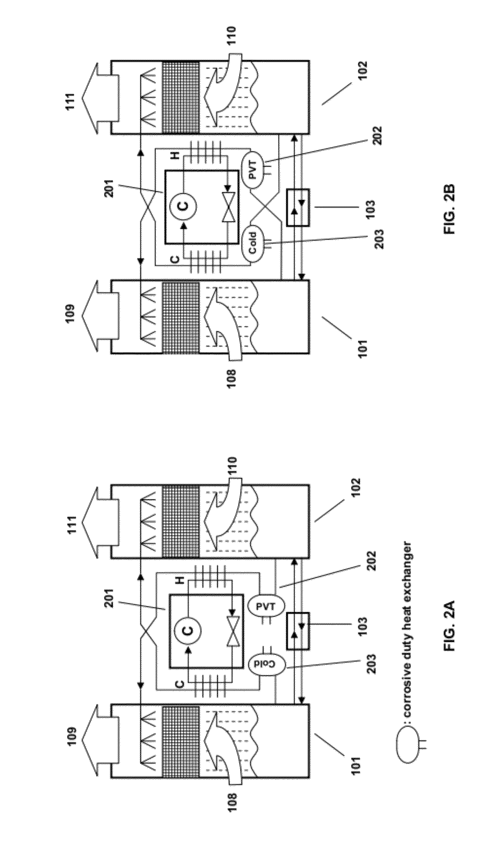
[0104]FIG. 1A depicts a liquid desiccant air conditioning system as known in the prior art. A desiccant conditioner 102 contains a liquid desiccant in a bath 104. The liquid desiccant 104 can be any suitable solution that attracts water vapor from the outdoor air 110 that is blown into the conditioner 102. The air moves through a filter media 106 that usually comprises a convoluted surface that easily holds and exposes the desiccant to the air stream. Examples of desiccants include CaCl2 and LiCl2. The filter media can be a cellulosic cooling tower fill material. Diluted desiccant 105 that has absorbed water drips from the filter media 106 into the desiccant bath 104. The spray head 107 distributes the concentrated desiccant evenly across the filter media 106. Dehumidified and cooled air 111 is directed into the building. A portion (usually around 10%) of the diluted desiccant 112 is brought through a heat exchanger 103 to a regenerator 101. The majority of the desiccant 112 is brou...


PUM

PropertyMeasurementUnit
temperaturesaaaaaaaaaa
temperatureaaaaaaaaaa
temperaturesaaaaaaaaaa

Abstract

Methods and systems are provided for air conditioning, capturing combustion contaminants, desalination, and other processes using liquid desiccants.

Description

CROSS REFERENCE TO RELATED APPLICATIONS[0001]This application claims priority from U.S. Provisional Patent Application Ser. No. 61 / 348,076, filed on May 25, 2010, entitled SOLAR AIR-CONDITIONING AND HEATING SYSTEMS, and U.S. Provisional Patent Application Ser. No. 61 / 430,692, filed on Jan. 7, 2011, entitled METHODS AND SYSTEMS FOR DESICCANT AIR CONDITIONING, both of which are hereby incorporated by reference.BACKGROUND[0002]The present application relates generally to air conditioning, capturing combustion contaminants, desalination, and other processes using liquid desiccants.[0003]The term “air conditioning” generally refers to the treatment of air going into a building space, including to the heating, cooling, humidity adjustment, or purification of air that enters or leaves the space. It is well known that air conditioning is an enormous source of energy use and that summer cooling in particular can lead to electricity grid problems. Air conditioning is often the largest operati...

Claims


Application Information

Patent Timeline
Patent Type & Authority Applications(United States)
IPC IPC(8): F25B43/00F25B27/00F25D31/00
CPCB01D53/263B01D2259/4508F24F3/1417Y10T29/49815H01L31/0422H01L31/0521H02S20/00Y02B10/70B01D53/14B01D53/1456B01D53/1475H02S40/00B01D2258/06B01D2257/40Y02E10/50Y02E10/60Y02B10/10H02S10/30H02S40/44F24F13/02F28D21/0015F28F3/10F28F19/00H01L31/042B01D2252/103F24F2003/1435F24F2003/144F24F2003/1458H01L31/052
Inventor VANDERMEULEN, PETER F.HANOKA, JACK I.HANOKA, CHAIM
Owner EMERSON CLIMATE TECH INC
Why Eureka
Eureka Blog
Learn More