
FERRITIC Cr-STEEL FOR HEAT-RESISTANT PRECISION COMPONENT AND METHOD FOR PRODUCING SAME, AND HEAT-RESISTANT PRECISION COMPONENT AND METHOD FOR PRODUCING SAME

Inactive Publication Date: 2012-05-31
NAT INST FOR MATERIALS SCI
View PDF1 Cites 0 Cited by
  • Summary
  • Abstract
  • Description
  • Claims
  • Application Information

AI Technical Summary

Benefits of technology

[0034]The ferritic Cr-steel for a heat-resistant precision component and the producing process thereof, and the heat-resistant precision component and the producing process thereof of the present invention realize a heat-resistant precision component for mechanical structures, as represented by turbines, used under high temperature. The heat-resistant precision component has high heat resistance (creep strength) while maintaining optimum low thermal expansion properties.

Problems solved by technology

This is because the ferritic Cr-steel, which undergoes small dimensional changes by thermal expansion, has low high-temperature strength, and undergoes creep deformation and changes the shape of the precision component.
However, the physical properties of the Ni-based superalloy do not allow the thermal expansion coefficient to be kept at values below that of the ferritic Cr-steel.
Indeed, there is a dilemma that the ferritic Cr-steel, with its small thermal expansion coefficient, has large creep deformation, and that the Ni-based superalloy, with its small creep deformation and high high-temperature strength, has a large thermal expansion coefficient.
Accordingly, it is considered very difficult to realize a heat-resistant precision component that can withstand use under high temperatures above 650° C. while undergoing only small changes in shape and dimension.[Patent Document 1] JP-A-2007-332412

Method used


Image

  • FERRITIC Cr-STEEL FOR HEAT-RESISTANT PRECISION COMPONENT AND METHOD FOR PRODUCING SAME, AND HEAT-RESISTANT PRECISION COMPONENT AND METHOD FOR PRODUCING SAME
  • FERRITIC Cr-STEEL FOR HEAT-RESISTANT PRECISION COMPONENT AND METHOD FOR PRODUCING SAME, AND HEAT-RESISTANT PRECISION COMPONENT AND METHOD FOR PRODUCING SAME
  • FERRITIC Cr-STEEL FOR HEAT-RESISTANT PRECISION COMPONENT AND METHOD FOR PRODUCING SAME, AND HEAT-RESISTANT PRECISION COMPONENT AND METHOD FOR PRODUCING SAME

Examples


examples

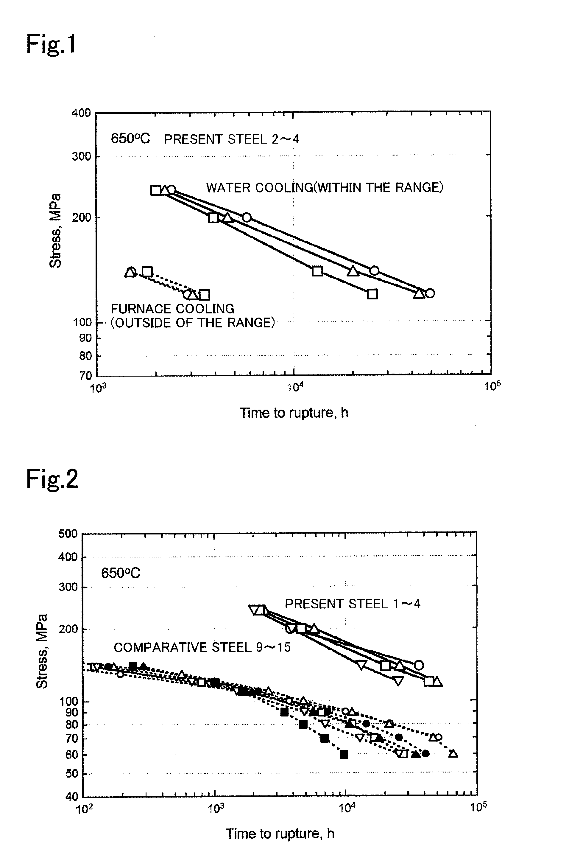
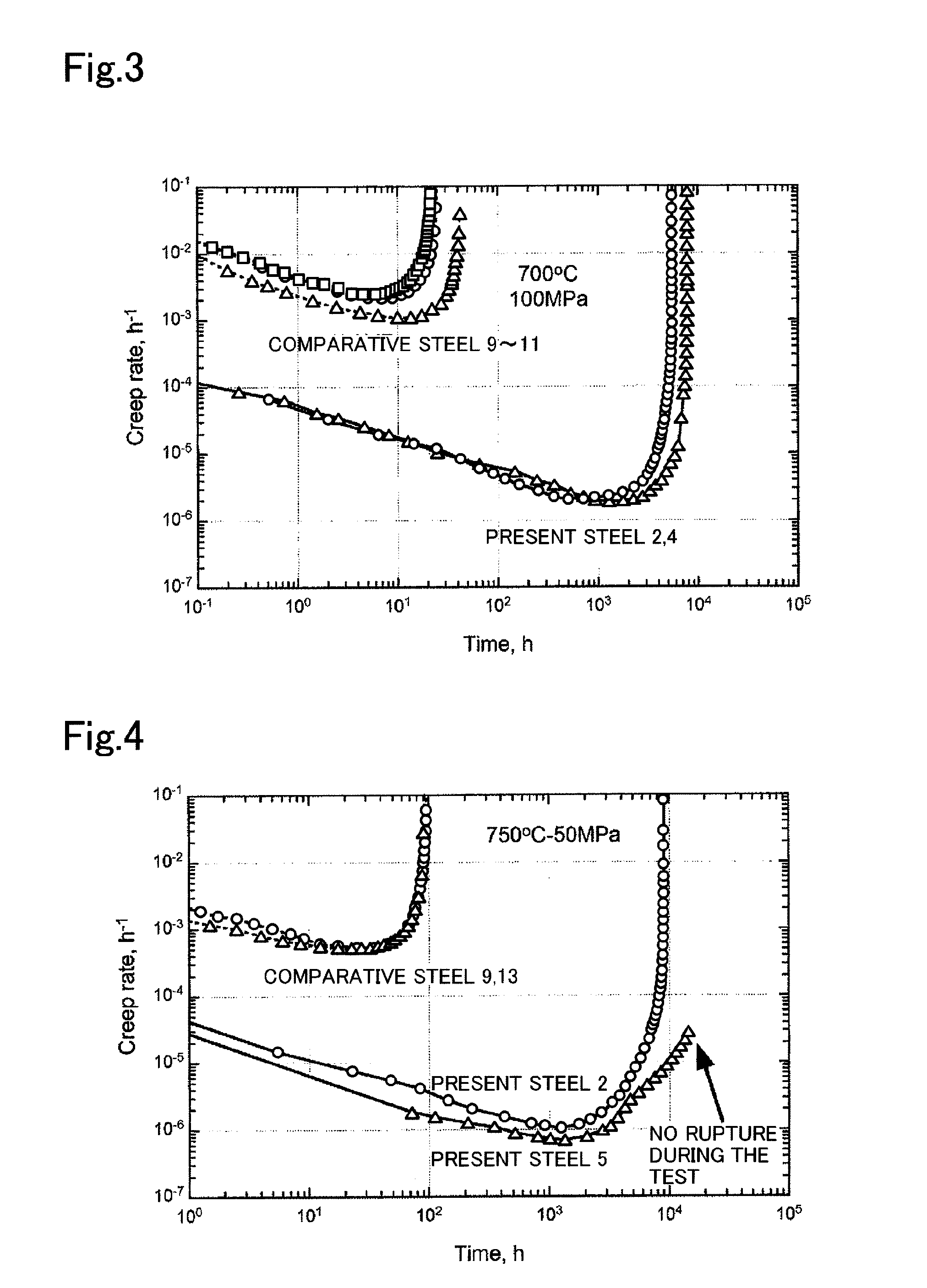
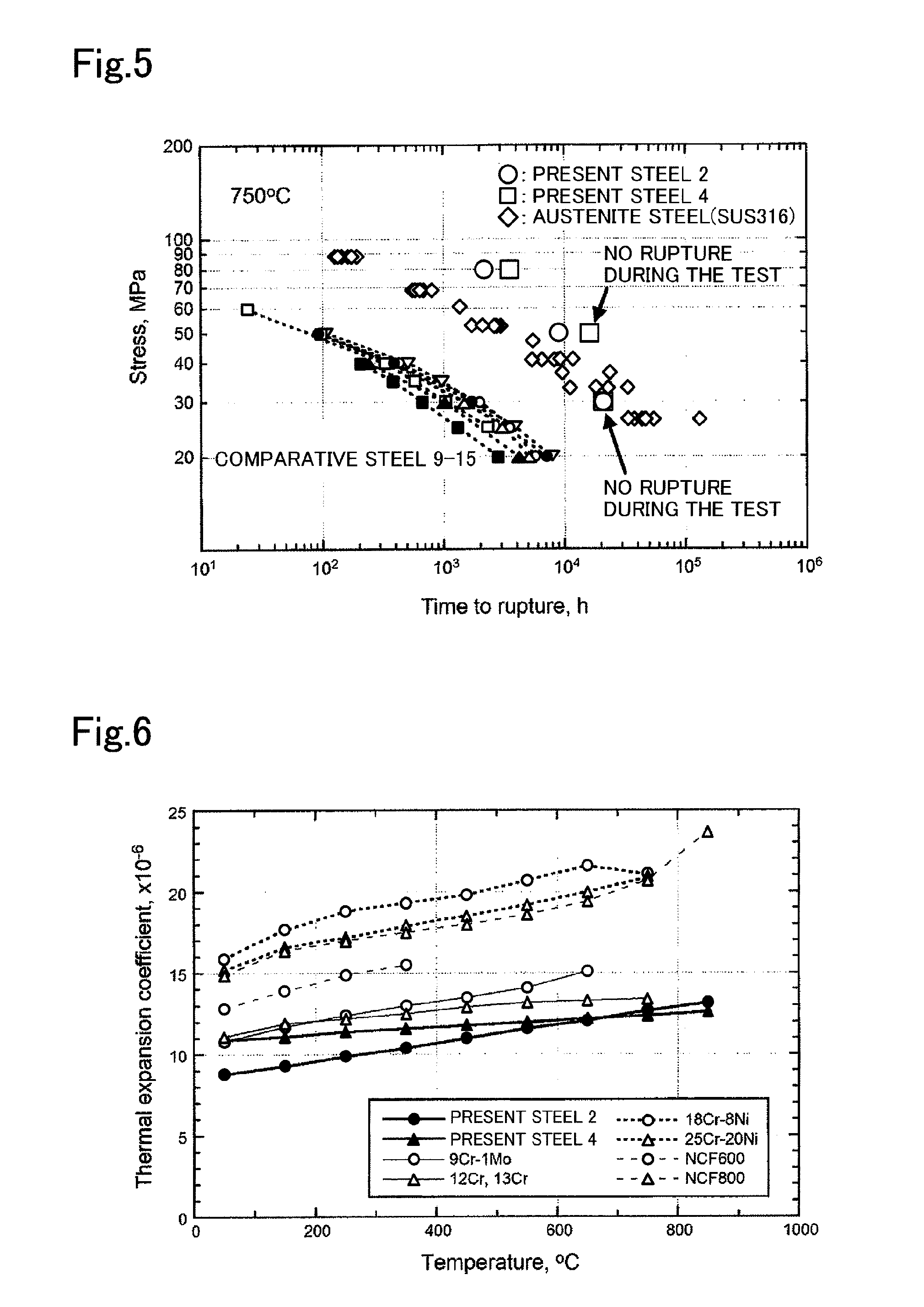
[0070]The round bars of steels 1 to 8 with the chemical compositions presented in Table 1 (steels 1 to 6 of the present invention, and comparative steels 7 and 8) were each prepared from a 10-kg steel ingot subjected to 850 to 1,150° C. hot forging to have a diameter of 15 mm. After 1,200° C. annealing treatment, each specimen was cooled by furnace cooling or water cooling.

[0071]Note that Table 1 also presents the chemical compositions of the existing ferritic heat-resistant steels (steels 9 to 15; comparative steels).

TABLE 1SpecimenComponent (Mass %)No.CSiMnNiCrMoVNbWCoNBFeThe10.0510.200.501.9914.940.990.200.0516.050.010.0410.0029Remainingpresent20.0490.200.511.2115.021.000.200.0516.042.960.0420.0028Remainingsteel30.0480.210.511.6015.001.000.200.0506.032.950.0440.0026Remaining40.0480.230.512.0014.960.990.200.0506.072.980.0360.0029Remaining50.0470.210.510.4214.931.000.200.0506.052.960.0410.0029Remaining60.0480.200.510.7815.001.000.200.0506.052.960.0420.0029RemainingComparative70.110...


PUM

PropertyMeasurementUnit
Temperatureaaaaaaaaaa

Abstract

A ferritic Cr-steel for a heat-resistant precision component contains Cr in an amount of from 13% by mass to 30% by mass, and has a thermal expansion coefficient of 15×10−6 or less in a temperature range of from room temperature to 800° C., and a minimum creep rate of 1×10⁻⁴ / h or less at 700° C. under stress of 100 MPa. The ferritic Cr-steel for a heat-resistant precision component is produced by hot working a ferritic Cr-steel in a temperature range of 850 to 1,200° C., forming the ferritic Cr-steel into a predetermined shape, subjecting the steel to an annealing treatment in a temperature range of 1,000 to 1,250° C., and cooling the steel to 400° C. or less at a cooling rate of 100° C. / min or higher. The production of the ferritic Cr-steel realizes a heat-resistant precision component, such as the rotor, disc, and blade of a turbine, that can withstand use under high temperatures above 600° C.

Description

TECHNICAL FIELD[0001]The present invention relates to ferritic Cr-steel used as material of precision components that have heat resistance.BACKGROUND ART[0002]Ferritic Cr-steel (also called ferritic high Cr-steel) is generally used as material of precision components that have heat resistance (hereinafter, referred to as “heat-resistant precision components), for example, such as the rotors, discs, and blades of machines such as steam turbines and gas turbines used under high temperature, because large thermal expansion coefficient differences cause positional misalignment relative to the other components.[0003]However, in face of the recent demand for use of turbines under high temperatures above 650° C., a Ni-based superalloy has been proposed as material of heat-resistant precision components, as described in Patent Document 1.[0004]This is because the ferritic Cr-steel, which undergoes small dimensional changes by thermal expansion, has low high-temperature strength, and undergo...

Claims


Application Information

Patent Timeline
IPC IPC(8): C21D8/00C22C38/54C22C38/48C22C38/52C22C38/44C22C38/46
CPCC21D6/004C21D2211/005C22C38/001C22C38/02C22C38/54C22C38/44C22C38/46C22C38/48C22C38/52C22C38/04
Inventor KIMURA, KAZUHIROTODA, YOSHIAKIKUSHIMA, HIDEAKISAWADA, KOTA
Owner NAT INST FOR MATERIALS SCI
Learn More