Detecting apparatus for detecting lightning strike, wind turbine blade equipped with the same, wind turbine generator, method for detecting lightning strike
a technology for detecting apparatus and wind turbine blades, which is applied in the installation of lighting conductors, electric generator control, instruments, etc., can solve the problems of difficult to detect which parts of damage to the wind turbine blades, and difficulty in immediate repairs, etc., to achieve simple, inexpensive, and high-reliability configuration
- Summary
- Abstract
- Description
- Claims
- Application Information
AI Technical Summary
Benefits of technology
Problems solved by technology
Method used
Image
Examples
first embodiment
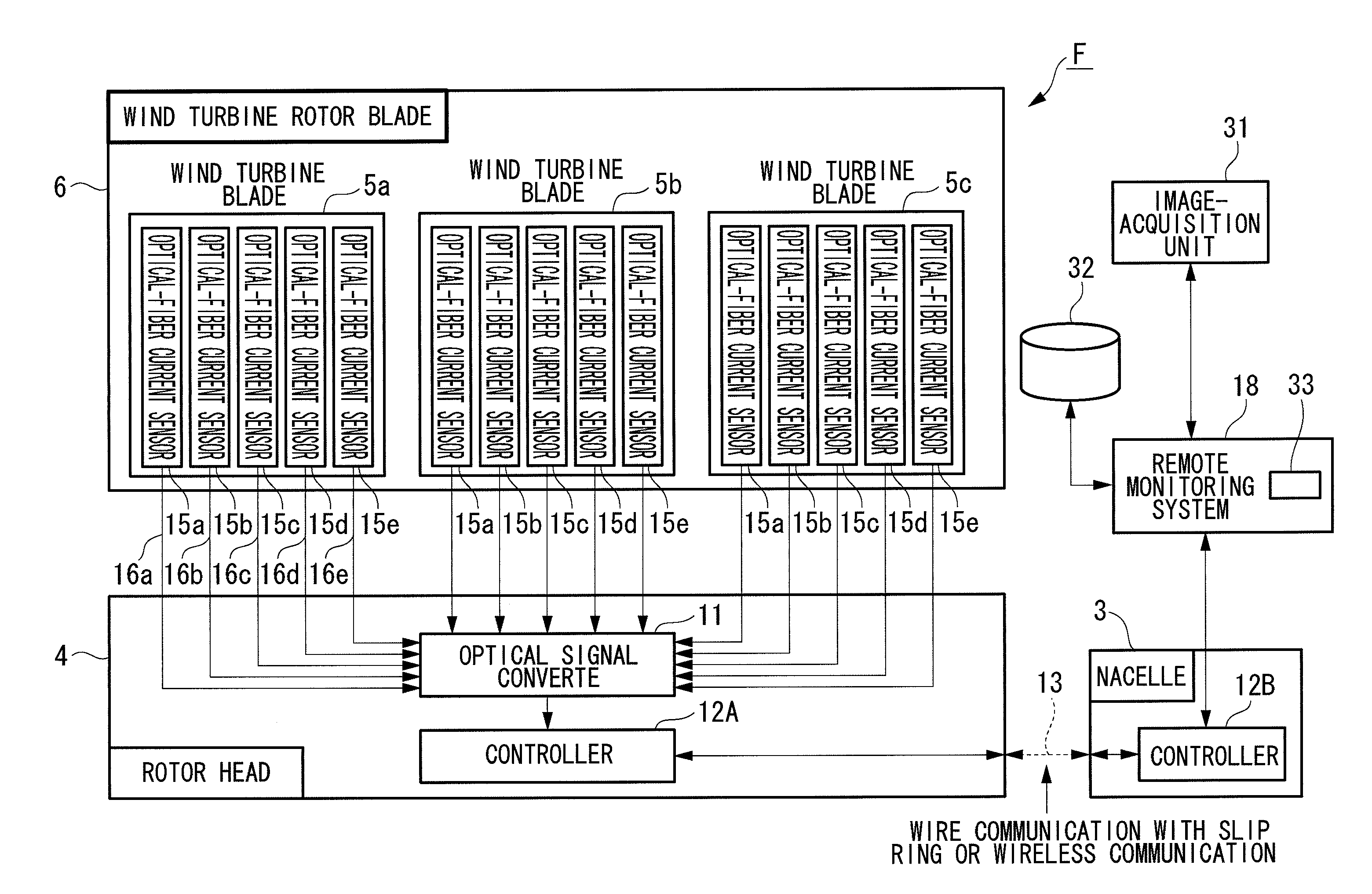
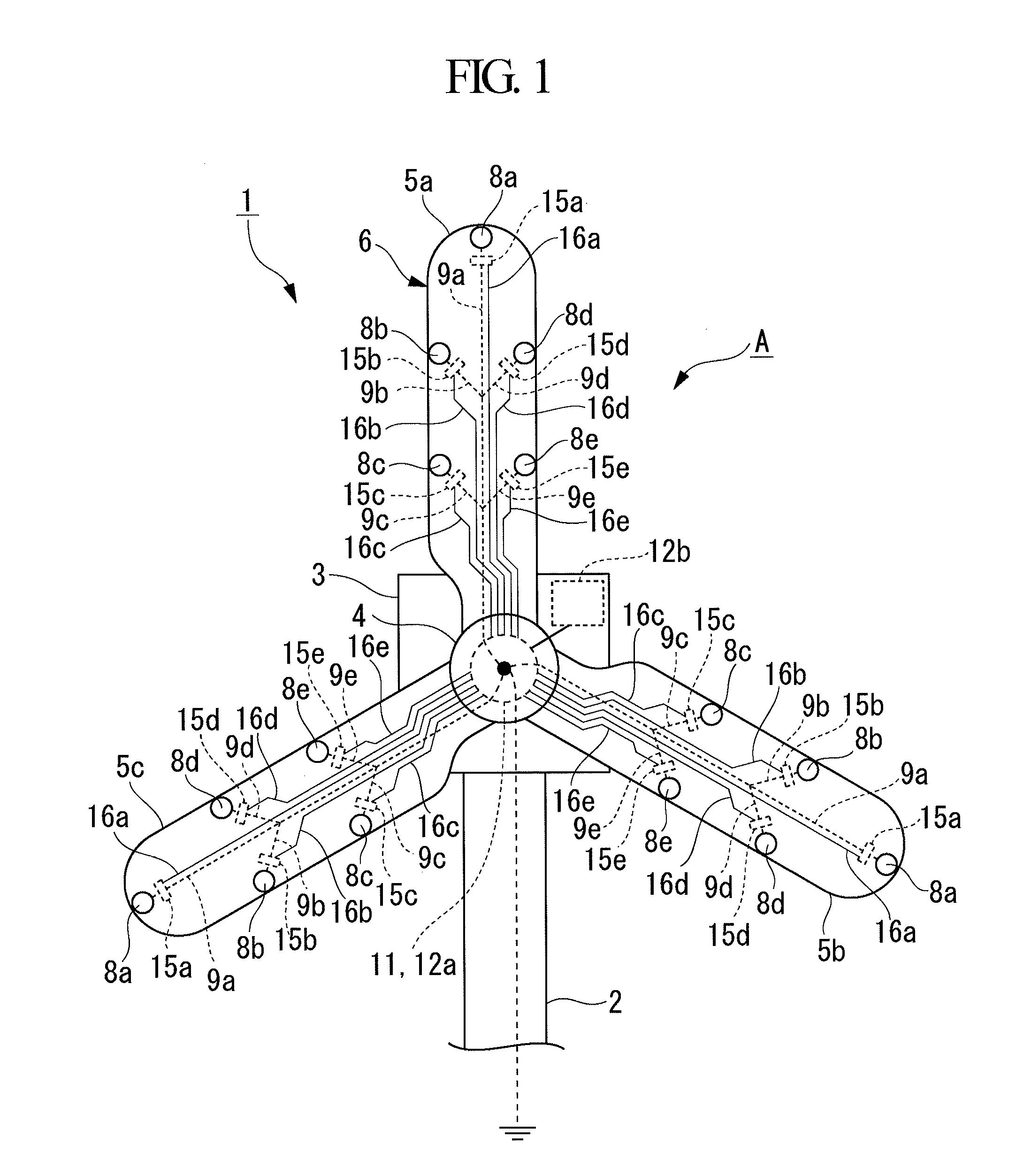
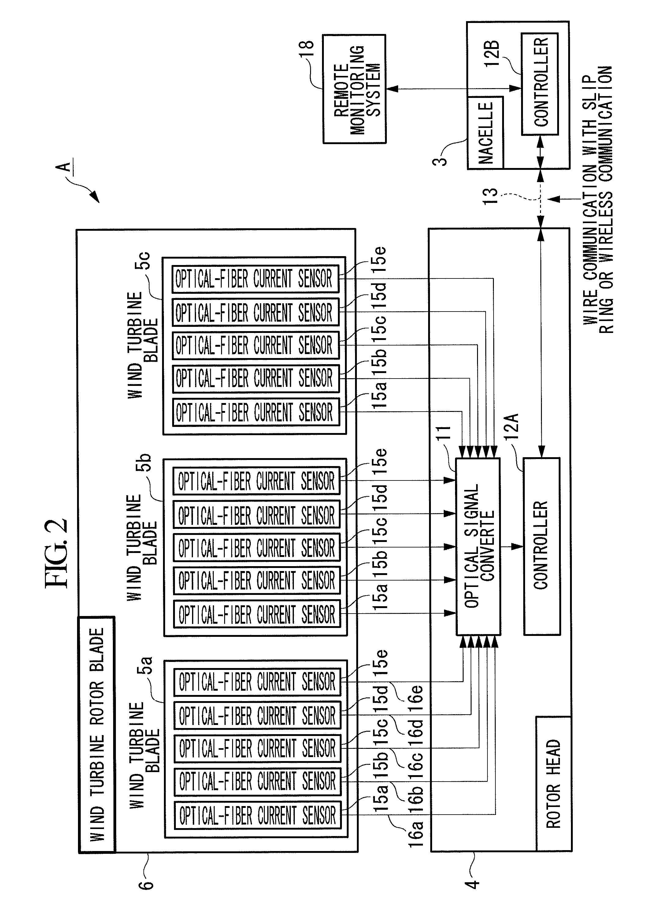
[0055]FIG. 1 is a front view showing an example of a wind turbine generator equipped with a wind turbine rotor blade to which a lightning-strike detecting apparatus A according to the present invention is applied. In addition, FIG. 2 is a block diagram showing, in outline, the configuration of the lightning-strike detecting apparatus A.
[0056]This wind turbine generator 1 includes a tower 2 disposed upright on, for example, the ground, ocean, or the like, a nacelle 3 disposed at the top end of the tower 2, and a rotor head 4 supported on the front end of the nacelle 3 so as to be freely rotatable around a rotational axis in an approximately horizontal transverse direction. A plurality of (e.g., three) radially extending wind turbine blades 5a, 5b, and 5c are attached to the rotor head 4 to form a wind turbine rotor blade 6, a generator (not shown) is accommodated inside the nacelle 3, and a rotor shaft of the rotor head 4 is connected to a main shaft of the above-mentioned generator ...
second embodiment
[0068]FIG. 4 is a perspective view of a lightning-strike detecting apparatus B showing a second embodiment of the present invention. In this embodiment, one unit of the receptor 8 is disposed only at the distal end of the wind turbine blades 5a to 5c, and three units, for example, of the optical-fiber current sensors 15a to 15c are disposed on one lightning conductor 9 extending from this receptor 8 to the blade root side. The optical fiber cables 16a, 16b, and 16c extending from the respective optical-fiber current sensors 15a to 15c are, similarly to the lightning-strike detecting apparatus A in the first embodiment, arranged together with the lightning conductor 9 inside the wind turbine blades 5a to 5c and connected to an optical signal converter that is installed inside the rotor head (not shown). The function of the optical-fiber current sensors 15a to 15c is the same as that in the lightning-strike detecting apparatus A. In addition, although not shown in the figure, similarl...
third embodiment
[0071]FIG. 5 is a perspective view of a lightning-strike detecting apparatus C showing a third embodiment of the present invention. In this embodiment, a total of five units of receptors 8a to 8e are disposed at the distal end and the intermediate portions of the wind turbine blades 5a to 5c, and the lightning conductors 9b, 9c, 9d, and 9e connected to the other receptors 8b to 8e are branched from the lightning conductor 9a extending from the receptor 8a provided at the distal end to the blade root side. A dedicated optical-fiber current sensor 15a is disposed on the lightning conductor 9a, a shared optical-fiber current sensor 15b is disposed on the lightning conductors 9b and 9c, and similarly, a shared optical-fiber current sensor 15c is disposed on the lightning conductors 9d and 9e. The optical fiber cables 16a, 16b, and 16c extending from the respective optical-fiber current sensors 15a, 15b, and 15c are arranged, together with the lightning conductors 9a, inside the wind tur...
PUM
 Abstract
Description
Claims
Application Information
 - R&D
- Intellectual Property
- Life Sciences
- Materials
- Tech Scout
- Unparalleled Data Quality
- Higher Quality Content
- 60% Fewer Hallucinations
Browse by: Latest US Patents, China's latest patents, Technical Efficacy Thesaurus, Application Domain, Technology Topic, Popular Technical Reports.
© 2025 PatSnap. All rights reserved.Legal|Privacy policy|Modern Slavery Act Transparency Statement|Sitemap|About US| Contact US: help@patsnap.com


