
LED illumination apparatus

a technology of led illumination apparatus and led diodes, which is applied in the direction of lighting and heating apparatus, semiconductor devices of light sources, planar light sources, etc., can solve the problems of insufficient illumination intensity in indoor or outdoor spaces, frequent replacement, etc., and achieves uniform illumination intensity, easy fabrication of led illumination apparatus, and improved productivity

Active Publication Date: 2012-05-31
SEOUL SEMICONDUCTOR
View PDF13 Cites 59 Cited by
  • Summary
  • Abstract
  • Description
  • Claims
  • Application Information

AI Technical Summary

Benefits of technology

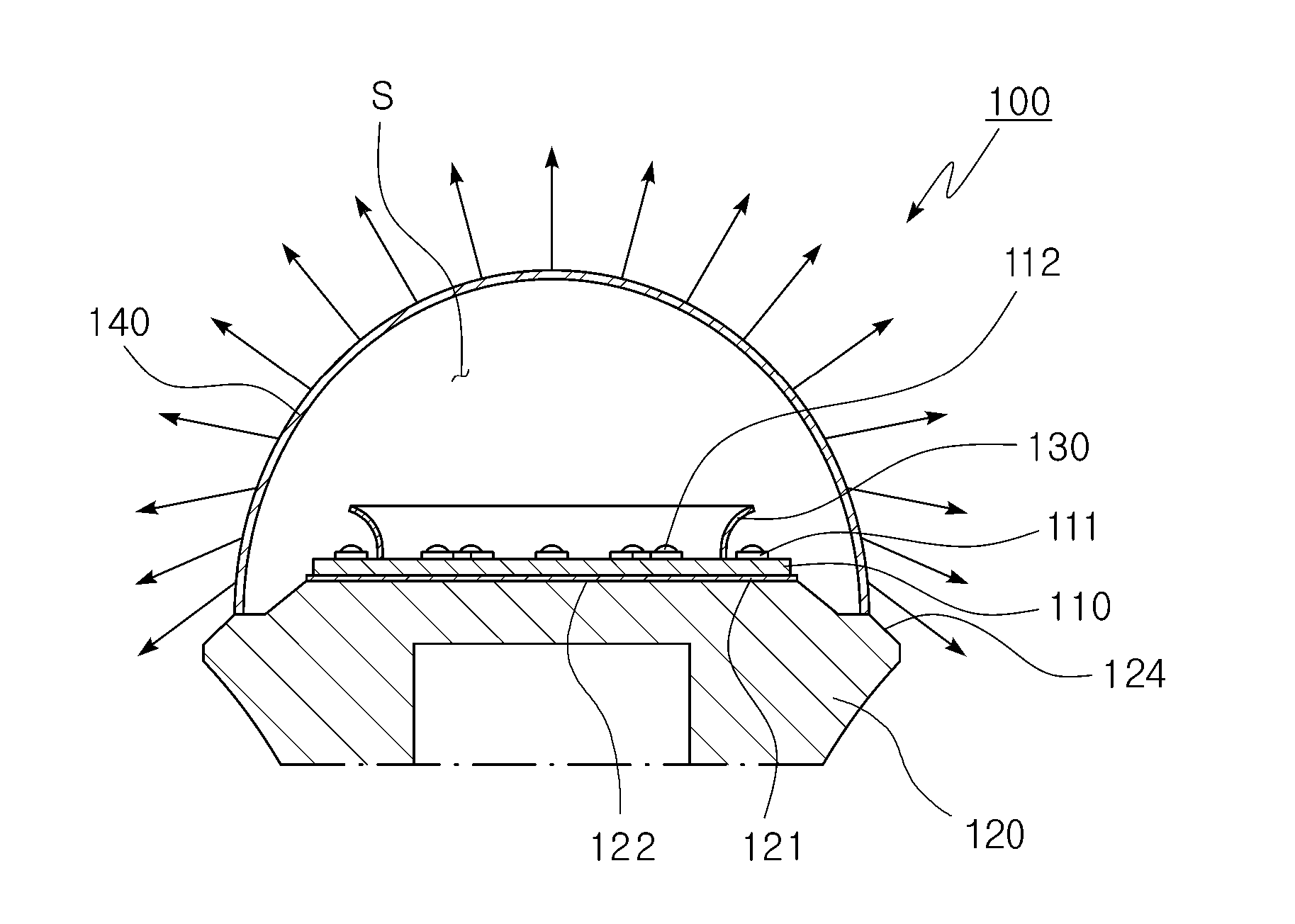
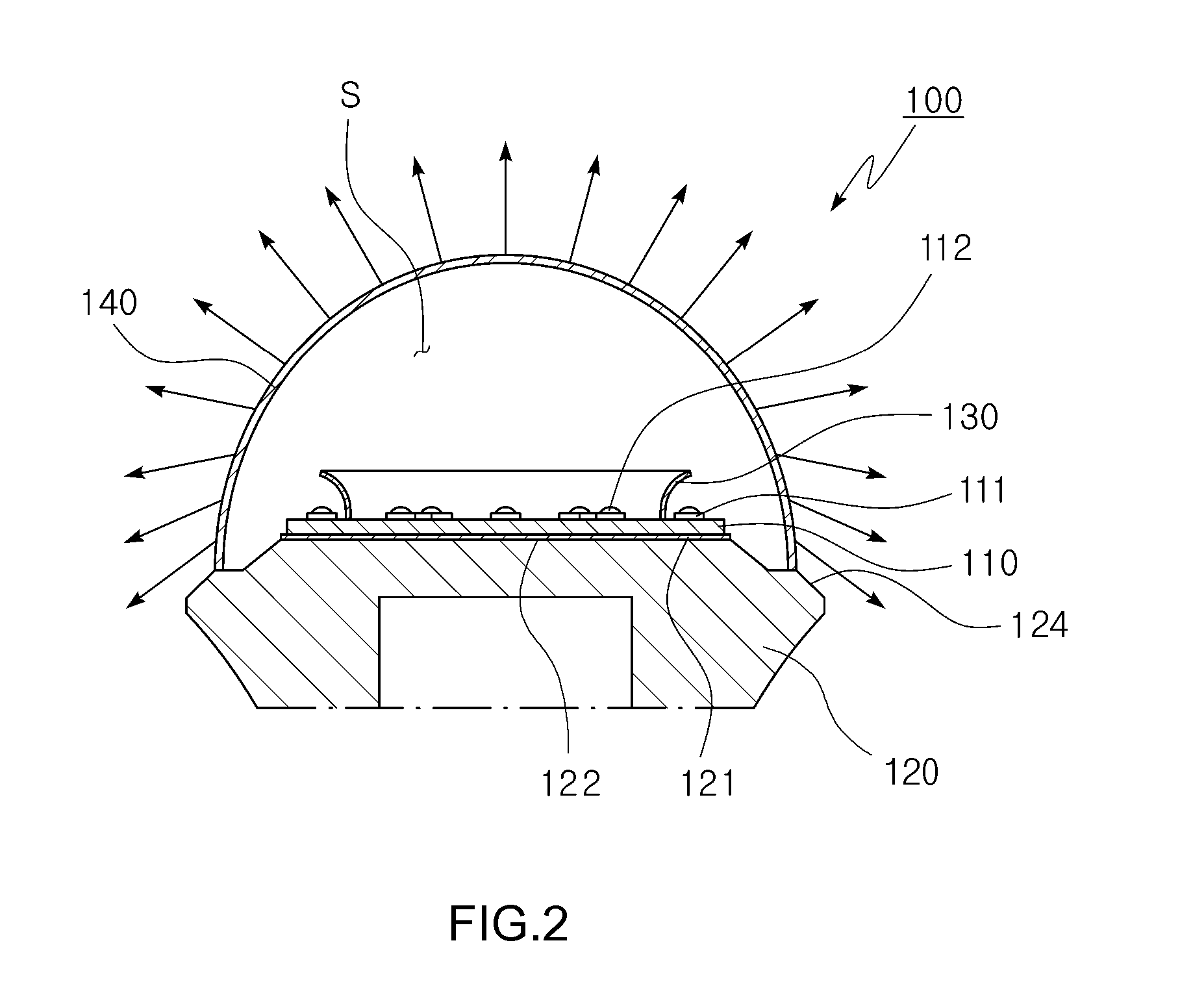
[0013]Exemplary embodiments of the present invention also provide an LED illumination apparatus that can achieve a wide light distribution with an increased angular range of radiation by directing a portion of the light that is generated by the light source to the side and rear of the illumination apparatus.
[0034]Moreover, it is possible to decrease the distance between the light source and the cover, which surrounds the light source, by forming the cover to be aspheric, so that the loss of the light that is radiated to the front is reduced, thereby increasing the entire light efficiency.

Problems solved by technology

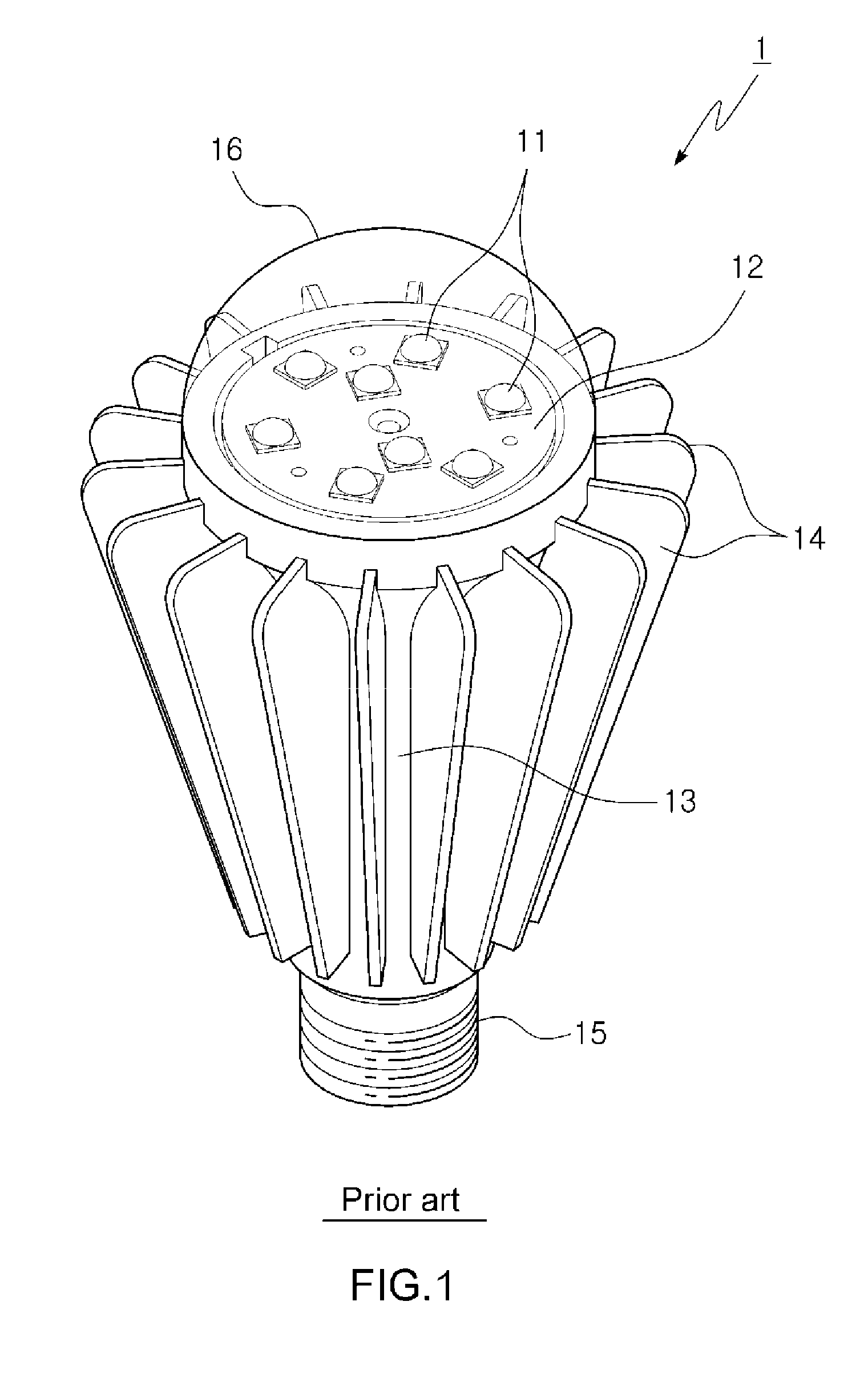
The incandescent lamps or fluorescent lamps have a problem in that they should be frequently replaced due to their short lifespan.
This causes a problem in that a sufficient intensity of illumination is not guaranteed in indoor or outdoor spaces.

Method used


Image

  • LED illumination apparatus
  • LED illumination apparatus
  • LED illumination apparatus

Examples


Embodiment Construction

[0087]The invention is described more fully hereinafter with reference to the accompanying drawings, in which embodiments of the invention are shown. This invention may, however, be embodied in many different forms and should not be construed as limited to the exemplary embodiments set forth herein. Rather, these exemplary embodiments are provided so that this disclosure is thorough, and will fully convey the scope of the invention to those skilled in the art. In the drawings, the size and relative sizes of layers and regions may be exaggerated for clarity. Like reference numerals in the drawings denote like elements.

[0088]It will be understood that when an element or layer is referred to as being “on” or “connected to” another element or layer, it can be directly on or directly connected to the other element or layer, or intervening elements or layers may be present. In contrast, when an element is referred to as being “directly on” or “directly connected to” another element or lay...


PUM

PropertyMeasurementUnit
areaaaaaaaaaaa
outer diameteraaaaaaaaaa
lengthaaaaaaaaaa

Abstract

An LED illumination apparatus realizes wide light distribution by increasing the angular range of radiation, and achieves uniform intensity of light through the arrangement of the position of a plurality of light sources. The LED illumination apparatus includes a substrate, a first light source disposed on a peripheral area of the substrate, a second light source disposed on an inner area of the substrate, and a reflector disposed between the first light source and the second light source, wherein the reflector is configured to reflect light that is generated by the first light source.

Description

CROSS REFERENCE TO RELATED APPLICATION[0001]This application claims priority from and the benefit of Korean Patent Application No. 10-2010-0118952, filed on Nov. 26, 2010, Korean Patent Application No. 10-2011-0020948, filed on Mar. 9, 2011, Korean Patent Application No. 10-2011-0021965, filed on Mar. 11, 2011, Korean Patent Application No. 10-2011-0049504, filed on May 25, 2011, and Korean Patent Application No. 10-2011-0090835, filed on Sep. 7, 2011, which are incorporated herein by reference for all purposes as if fully set forth herein.BACKGROUND OF THE INVENTION[0002]1. Field of the Invention[0003]Exemplary embodiments of the present invention relate to a light emitting diode (LED) illumination apparatus, and more particularly, to an LED illumination apparatus which may realize wide light distribution by increasing the angular range of radiation and achieve uniform intensity of light and a variety of light distribution patterns to reduce the loss of light that is generated by a...

Claims


Application Information

Patent Timeline
Patent Type & Authority Applications(United States)
IPC IPC(8): F21V9/16F21V29/00F21V7/00
CPCF21K9/135F21V29/74F21K9/56F21V3/00F21V7/0016F21V9/16F21V13/02F21Y2101/02F21Y2103/022F21Y2105/001F21Y2111/008F21V7/00F21V29/20F21V7/0058F21V17/101F21V17/12Y10S362/80F21V3/02F21V29/70F21K9/50F21Y2105/12F21Y2105/10F21K9/232F21K9/60F21K9/62F21K9/64F21Y2115/10F21Y2103/33F21Y2107/60F21K9/238F21V3/10F21V23/005F21V5/00F21V13/08F21V3/12F21V9/38F21V7/09F21V7/22F21Y2101/00F21V3/049F21V7/04F21Y2107/80
Inventor KANG, KI TAE
Owner SEOUL SEMICONDUCTOR
Learn More