Methods of preparing electrocatalysts for fuel cells in core-shell structure and electrocatalysts
- Summary
- Abstract
- Description
- Claims
- Application Information
AI Technical Summary
Benefits of technology
Problems solved by technology
Method used
Image

Examples
example 1-1 (
Pd / C)
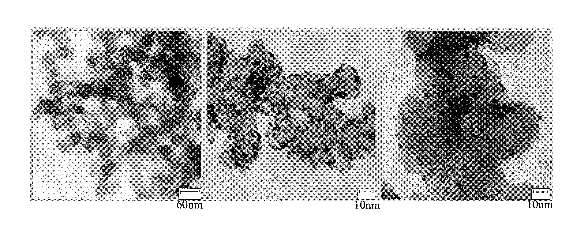
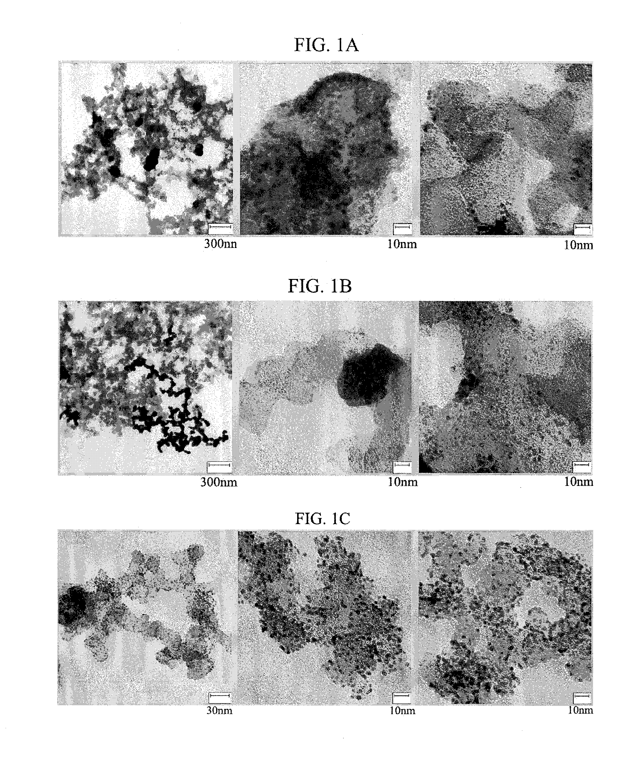
[0069]Carbon Vulcan-XC 72R was used as a support, and palladium acetylacetonate (Pd(acac)2) 121.9 mg, which is a precursor of a metal for forming a core, and t-butylamine borane 600 mg, which is a reducing agent, were reacted in a solvent benzyl ether 100 mL. The resulting reaction mixture was reacted at room temperature for 10 hours. A TEM photograph of the prepared core support was taken (FIG. 3A).
example 1-2 (
Pd / C)
[0070]A core support was prepared in the same manner as in Example 1-1, except that the reaction was performed at a temperature of 100° C. A TEM photograph of the prepared core support was taken (FIG. 3B).
Example 1-3 (Pd3Cu1 / C)
[0071]A core support was prepared in the same manner as in Example 1-1, except that palladium acetylacetonate (Pd(acac)2) 119.4 mg and copper acetylacetonate (Cu(acac)2) 34.2 mg were used as the precursors of the metal for forming a core. A TEM photograph of the prepared core support was taken (FIG. 3C).
[0072]When the TEM photographs of the core supports prepared in Comparative Examples and Examples were compared to one another, it was seen that the core particles having a nanosize diameter were not suitably formed in the case of Comparative Examples 1-1 and 1-2 in which the diol was used as the solvent. Meanwhile, it was revealed that the core particles having a nanosize diameter were formed and had excellent uniformity in the case of Comparative Example...
example 2-2 (
Pd@Au@Pt / C)
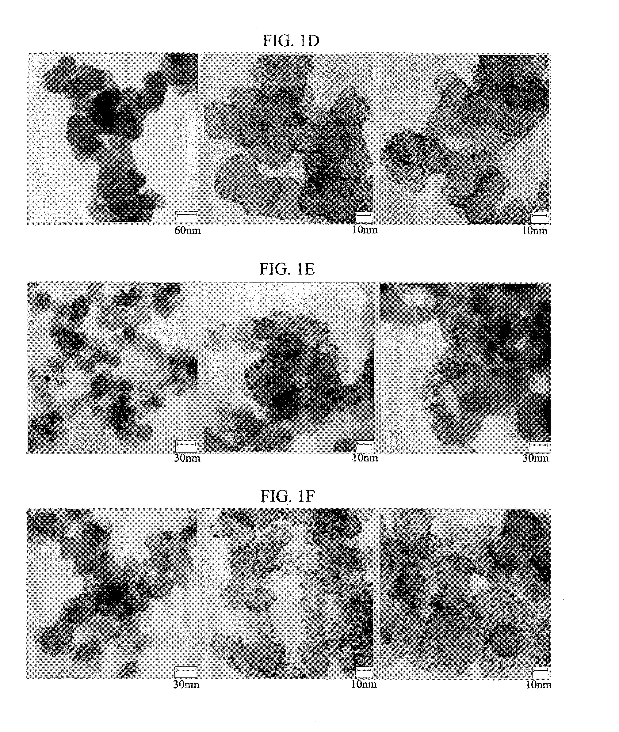
[0079]Shell layers were formed from 93.2 mg (1.1 eq of a core) of hexachloroplatinic acid (H2PtCl6.6H2O, alfa aesar) and 23.6 mg (0.375 eq of a core) of HAuCl4.3H2O, both of which were dissolved in 50 ml of absolute ethanol, in a solution obtained by sufficiently dispersing 50 mg of the core support prepared in Example 1-2 in 150 ml of absolute ethanol. Hanztsch ester (5 eq of a Pt precursor, 1.2 mmol) (Formula 4) dissolved in 20 ml of absolute ethanol was used as the reducing agent. The reaction was performed at a temperature of 80° C. for 2 hours.
[0080]Comparing the core-shell structures (FIGS. 4A and 4B) of Comparative Example 2 and Example 2-1a, the metal for forming a shell layer was coated on surfaces of the core particles as well as a region of the support to form shell layers on the whole support when the metal precursor was reduced with ascorbic acid in Comparative Example 2. On the other hand, when the Hanztsch ester of the present invention was used, it was con...
PUM
| Property | Measurement | Unit |
|---|---|---|
| Current density | aaaaa | aaaaa |
| Current density | aaaaa | aaaaa |
| Current density | aaaaa | aaaaa |
Abstract
Description
Claims
Application Information
PatSnap Eureka turns technology decisions into work you can execute. Powered by our Innovation Knowledge Graph, it runs expert workflows across engineering, life sciences, materials and intellectual property. Get your review-ready output in minutes.


