
Ultrasound diagnostic apparatus and control method thereof

a technology of ultrasound and diagnostic equipment, applied in the field of ultrasound diagnostic equipment, can solve the problems of increasing the time it takes to acquire an ultrasound image, and achieve the effect of improving the picture quality of images

Active Publication Date: 2012-05-31
SAMSUNG ELECTRONICS CO LTD +1
View PDF1 Cites 6 Cited by
  • Summary
  • Abstract
  • Description
  • Claims
  • Application Information

AI Technical Summary

Benefits of technology

[0008]Exemplary embodiments provide an ultrasound diagnostic apparatus to improve picture quality of images by automatically adjusting image parameters, and a control method thereof.
[0012]The TGC processor may adjust the linear fitting curve using a mean value of a discontinuous curve region so as to eliminate the discontinuous curve region when the discontinuous curve region is present on the linear fitting curve.
[0015]The TGC processor may lower a size of the envelope detection processed ultrasound image data by dividing the envelope detection processed ultrasound image data judged to be noise by a second reference value when the envelope detection processed ultrasound image data is judged to be noise.
[0020]The DR processor may adjust the DR parameter by increasing the high value as the difference between the mean value and the median value is increased.
[0026]The control method may further include adjusting the linear fitting curve using a mean value of a discontinuous curve region so as to eliminate the discontinuous curve region when the discontinuous curve region is present on the linear fitting curve.

Problems solved by technology

In a conventional ultrasound diagnostic apparatus, a user must directly fine-tune image parameters minutely in order to acquire an optimal ultrasound image, thereby causing fatigue and increasing time to acquire an ultrasound image due to a complicated control procedure.

Method used


Image

  • Ultrasound diagnostic apparatus and control method thereof
  • Ultrasound diagnostic apparatus and control method thereof
  • Ultrasound diagnostic apparatus and control method thereof

Examples


Embodiment Construction

[0040]Reference will now be made in detail to the exemplary embodiments, examples of which are illustrated in the accompanying drawings.

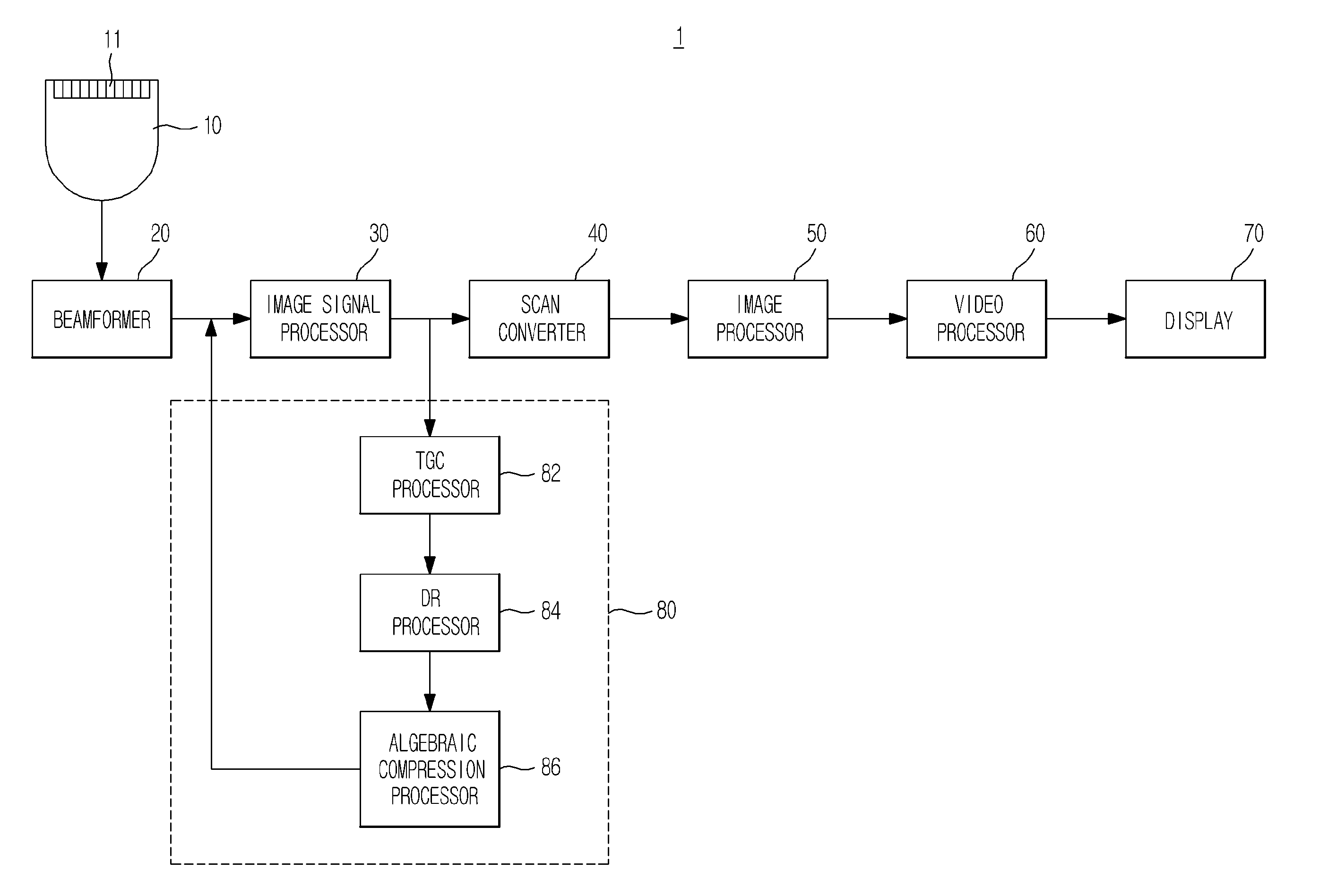
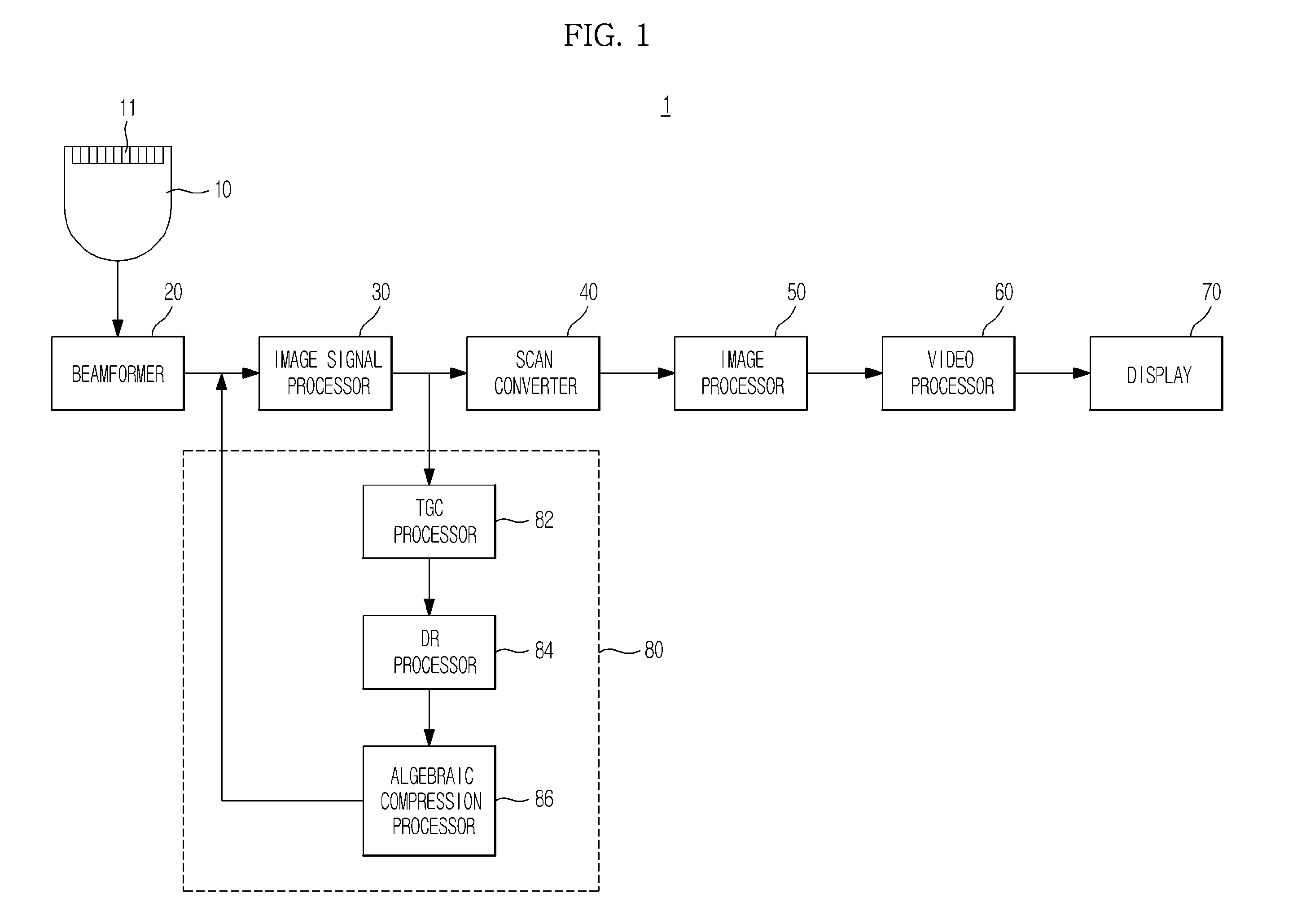
[0041]FIG. 1 is a block diagram of an ultrasound diagnostic apparatus according to an exemplary embodiment.

[0042]An ultrasound diagnostic apparatus 1 may include a probe 10, a beamformer 20, an image signal processor 30, a scan converter 40, an image processor 50, a video processor 60, a display 70, and an image parameter processor 80. The image signal processor 30, the image processor 50, the video processor 60, and the image parameter processor 80 may be integrated into at least one processor.

[0043]The probe 10 may include a plurality of one or two-dimensional transducers 11. The probe 10 appropriately delays input times of pulses input to the respective transducers 11 to transmit a focused ultrasound beam to an object (not shown) along a transmission scan line. Ultrasound echo signals reflected from the object are input to the respective transduc...


PUM


Abstract

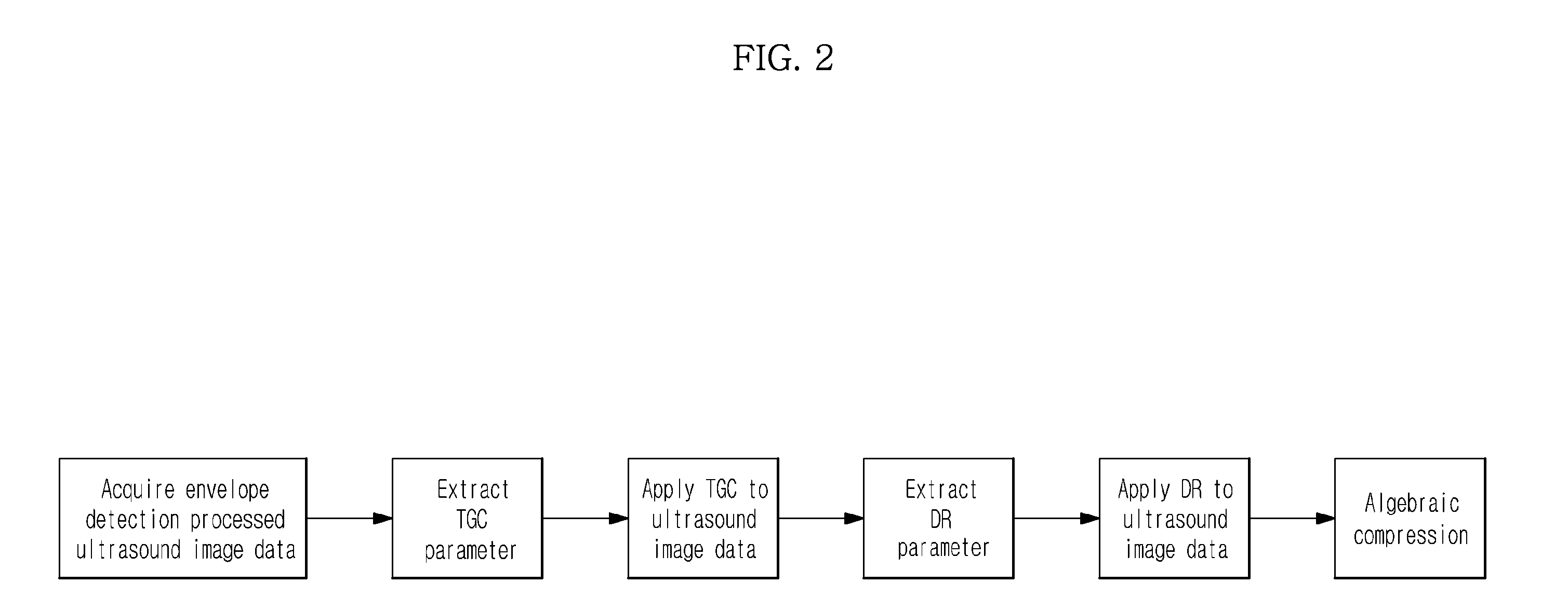
An ultrasound diagnostic apparatus to improve picture quality of images by automatically adjusting image parameters, and a control method thereof are provided. The ultrasound diagnostic apparatus includes an image signal processor to perform envelope detection processing on ultrasound image data, and an image parameter processor to calculate a Time Gain Compensation (TGC) parameter from the envelope detection processed ultrasound image data, adjust the envelope detection processed ultrasound image data based on the TGC parameter, and calculate a Dynamic Range (DR) parameter from the envelope detection processed ultrasound image data adjusted based on the TGC parameter to apply the DR parameter to the envelope detection processed ultrasound image data.

Description

CROSS-REFERENCE TO RELATED APPLICATION[0001]This application claims priority from Korean Patent Application No. 10-2010-0117786, filed on Nov. 25, 2010 in the Korean Intellectual Property Office, the disclosure of which is incorporated herein by reference.BACKGROUND[0002]1. Field[0003]Apparatuses and methods consistent with exemplary embodiments relate to an ultrasound diagnostic apparatus, and a control method thereof.[0004]2. Description of the Related Art[0005]An ultrasound diagnostic apparatus is one of important diagnostic systems which have a wide variety of applications. Especially, ultrasound systems are used extensively in the field of medicine due to the noninvasive and nondestructive nature with respect to an object. Recent high-performance ultrasound systems are used to generate two- or three-dimensional images of the interior of an object.[0006]To observe an object, it is necessary to acquire an optimal ultrasound image which shows the object clearly. To this end, an ul...

Claims


Application Information

Patent Timeline
IPC IPC(8): A61B8/14
CPCA61B8/08G01S7/52033A61B8/54A61B8/5207
Inventor KIM, KANG SIKSONG, TAI KYONGCHANG, JIN HOYOO, YANG MOSONG, JAE HEEJIN, SEONG MINKIM, CHOYE
Owner SAMSUNG ELECTRONICS CO LTD
Learn More