
Radiation treatment planning system and computer program product

Inactive Publication Date: 2012-05-31
DEUTES KREBSFORSCHUNGSZENT STIFTUNG DES OFFENTLICHEN RECHTS
View PDF2 Cites 30 Cited by
  • Summary
  • Abstract
  • Description
  • Claims
  • Application Information

AI Technical Summary

Benefits of technology

[0023]Accordingly, due to the system of the invention, the radiotherapist can interact with the treatment planning system such as to step by step improve the treatment plan. This is for example advantageous in cases where a fairly good treatment plan for example obtained by a prior art optimization method is available but only some local hot spots or cold spots need to be corrected for, or where some local changes are necessary due to a change of patient geometry, for example due to tumor growth. However, the concept of local dose shaping even allows to devise the treatment plan interactively completely from scratch.
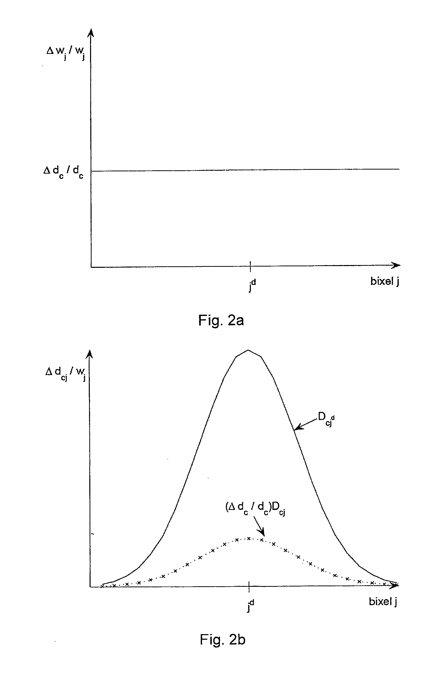
[0044]In a preferred embodiment, the system is configured to perform, in response to an inputted dose variation, a sequence of alternating local dose variation and dose recovery steps, wherein in each of the local dose variation steps, the local dose variation is performed for a predetermined fraction of the inputted local dose variation value only. This embodiment is an “adiabatic” approach, where the local change of dose prescribed by the user will be split up in a number of steps of smaller local dose variation with dose recovery steps inbetween. It has been confirmed in experiment that this adiabatic approach allows for a very smooth and stable convergence of the local dose shaping.

Problems solved by technology

However, unfortunately in practice the problem to be solved is the other way around: Based on detailed knowledge of the patient geometry from CT or MRT images, the radiooncologist prescribes a certain dose distribution within the target area and certain dose constraints in the organs at risk, and the problem is to find the corresponding bixel weights to achieve this.
Such iterative search can take between several minutes and several hours due to the complexity of the problem.
While such prior art optimization modules have been extremely useful in devising treatment plans, there are still a number of problems remaining.
However, the global optimization often cannot prevent adverse local effects in the treatment plan.
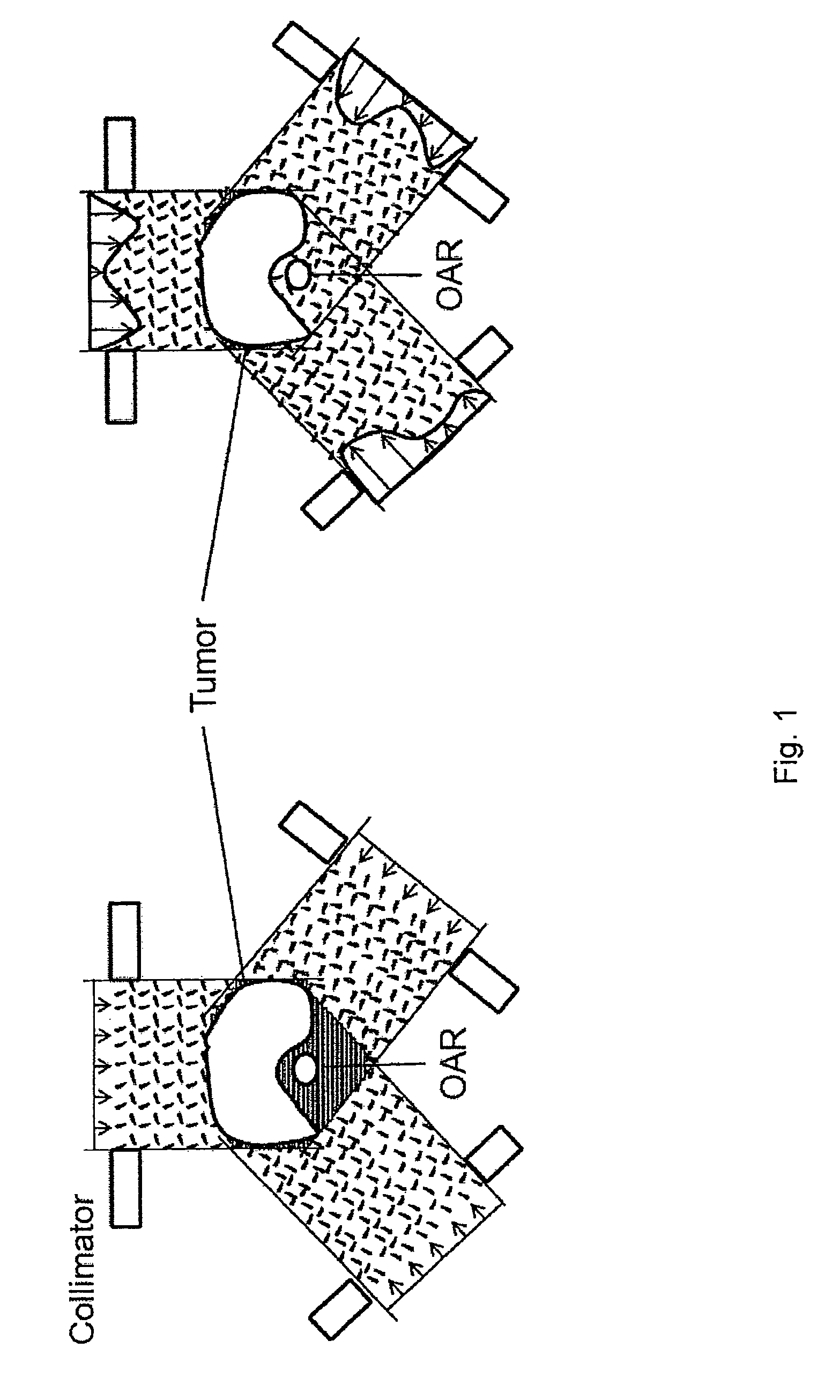
An example for such local effects are hot spots, i.e. strictly localized dose maxima, which due to their strict locality have only little influence on the cost functions used in the optimization scheme but are of course clinically prohibitive.
Another problem involved with prior art global optimization modules is that due to extended computation time, the treatment plan has to be calculated well in advance of the actual treatment and is therefore often based on medical images that have been taken several days or even weeks prior to the treatment.
If the patient geometry changes between taking the planning images and the actual therapy, for example due to tumor growth, the treatment plan may no longer be quite suitable.
Accordingly, the prior art optimization modules lack flexibility and interaction with the radiotherapist.
However, such manual adjustment is again difficult to perform, because any adjustment of a bixel to correct a dose locally will also have an effect on the dose distribution at other sites.
In fact, due to the complexity and the inherent synergistic effect of IMRT, a suitable manual revision of the treatment plan is rather difficult to perform.
Due to the high synergistic effect of methods like IMRT, a local dose variation to the better will generally lead to a change of dose at a remote site to the worse.
However, at the same time more unwanted dose deviation may occur in uninvolved voxels within a wide location around the local dose variation site.

Method used


Image

  • Radiation treatment planning system and computer program product
  • Radiation treatment planning system and computer program product
  • Radiation treatment planning system and computer program product

Examples


Embodiment Construction

[0059]For the purposes of promoting an understanding of the principles of the invention, reference will now be made to the preferred embodiment illustrated in the drawings and specific language will be used to describe the same. It will nevertheless be understood that no limitation of the scope of the invention is thereby intended, such alterations and further modifications in the illustrated system and such further applications of the principles of the invention as illustrated therein being contemplated as would normally occur now or in the future to one skilled in the art to which the invention relates.

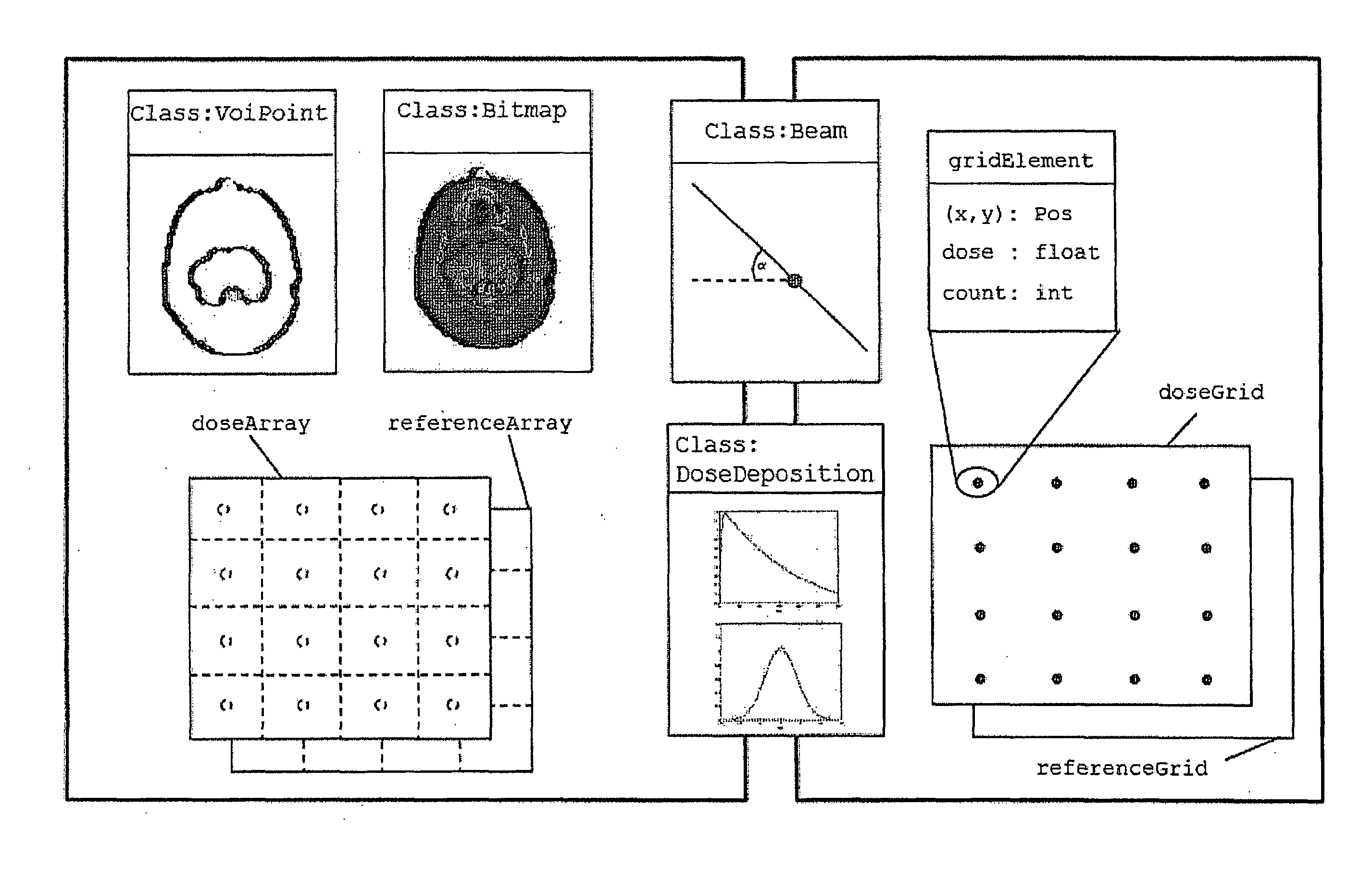
[0060]In the following, a preferred embodiment of a radiation treatment planning system according to the present invention will be described. To begin with, however, the underlying concept of local dose shaping, the preferred data structure used and a work flow of local dose shaping employed in the planning system will be explained in detail.

[0061]The Concept of Local Dose Shaping

[0...


PUM


Abstract

The present invention relates to a radiation treatment planning system and a corresponding computer program product. The system comprises means for graphically displaying an image representing a target area 10 to be treated with a set o therapeutic radiation beams and an adjacent structure comprising healthy tissue 14 and / or organs at risk 12, and for displaying corresponding dose values according to a preliminary treatment plan. The system further comprises means for allowing a user to interactively input a local dose variation, local dose variation means for revising the preliminary treatment plan such as to account for the local dose variation inputted by the user and dose recovery means comprising means for revising the treatment plan again such as to at least partially compensate for a change of dose in a predetermined recovery area caused by said dose variation.

Description

BACKGROUND OF THE INVENTION[0001]1. Field of the Invention[0002]The present invention relates generally to radiation therapy. More specifically, the present invention relates to a system and a computer program product for radiation treatment planning.[0003]2. Description of the Related Art[0004]Radiation therapy can be effective in treating cancers, tumors, lesions or other targets. Many tumors can be eradicated completely if a sufficient radiation dose is delivered to the tumor body such as to destroy the tumor cells. The maximum dose which can be applied to a tumor is determined by the tolerance dose of the surrounding healthy tissue. With the development of computer tomography (CT) and magnet resonance tomography (MRT), sophisticated insight into the body of the patient has been given. Supported by the increasing availability of high-performance computers, a new generation of treatment planning systems for a conformal 3D-therapy technique has been developed which allows to increa...

Claims


Application Information

Patent Timeline
IPC IPC(8): G06Q50/22G16H20/40
CPCA61N5/1031G06Q50/22A61N5/1042G16H20/40
Inventor ZIEGENHEIN, PETEROELFKE, UWE
Owner DEUTES KREBSFORSCHUNGSZENT STIFTUNG DES OFFENTLICHEN RECHTS
Learn More