High Aspect Ratio Microelectrode Arrays Enabled to Have Customizable Lengths and Methods of Making the Same

a microelectrode array and length technology, applied in the field of microelectrode array devices and fabrication methods, can solve the problems of inability to probe and stimulate neurons in complex three-dimensional environments, limited electrode placement and length, and inability to produce satisfactory needles by simply using conventional electrode formation processes, etc., and achieve ultra-high aspect ratio electrodes.

Active Publication Date: 2012-06-07
UNIV OF UTAH RES FOUND
View PDF17 Cites 26 Cited by
  • Summary
  • Abstract
  • Description
  • Claims
  • Application Information

AI Technical Summary

Benefits of technology

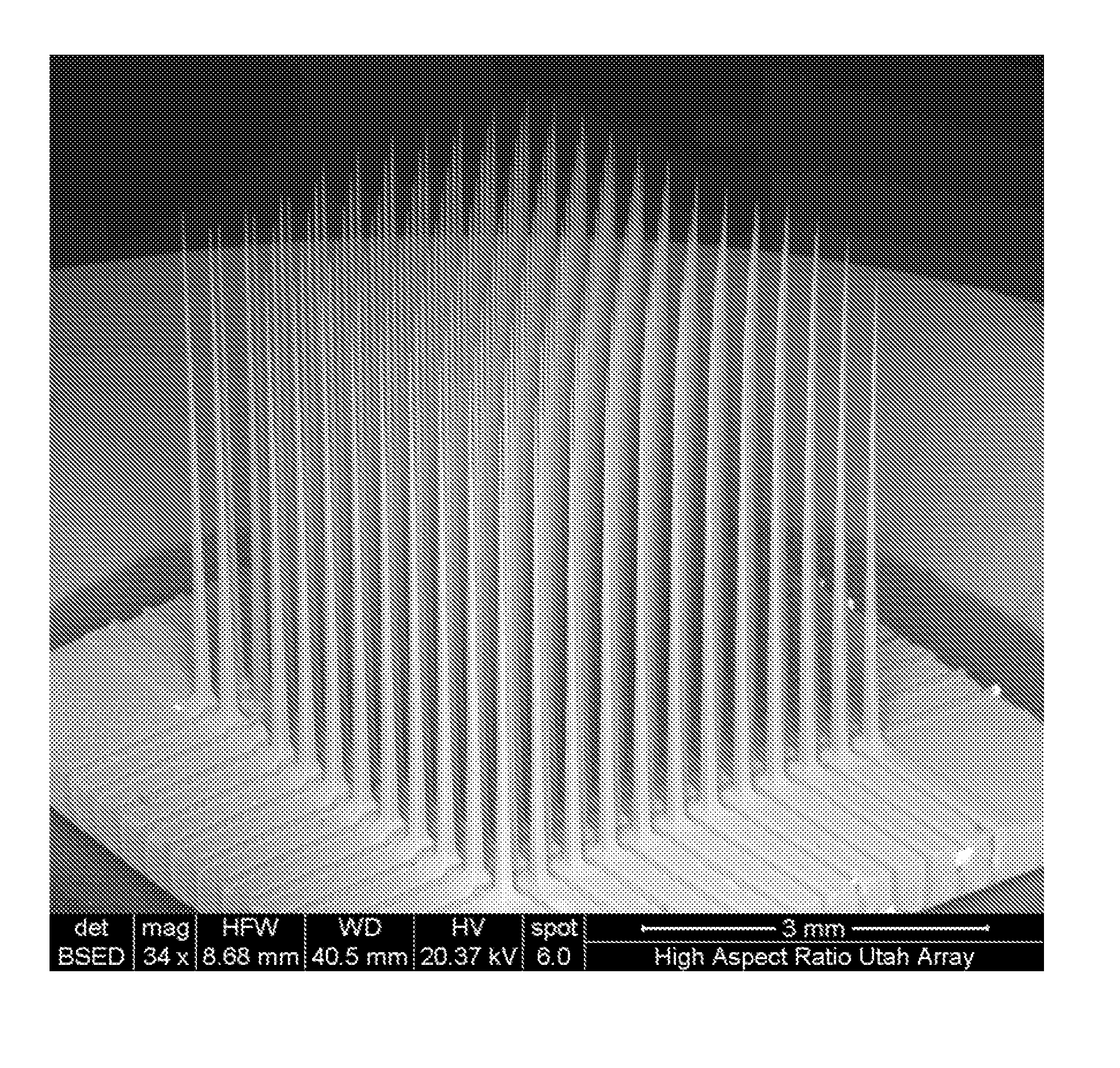
[0004]The ability to probe and stimulate neurons in complex three-dimensional environments is currently limited by the placement and lengths of electrodes. It has been recognized that longer electrodes would be useful in expanding options for research and neuro-prosthetic therapies. Unfortunately, merely using conventional electrode formation processes does not produce satisfactory needles when lengths are extended beyond about 1.5 to 2 mm (with a base footprint of 16 mm2). FIG. 1 illustrates an attempt by the inventors to use standard Utah Electrode Array (UEA) processing to obtain ultra-high aspect ratio electrodes. As can be seen in this micrograph, several of the needles are either missing or have severe narrowing near the base making the electrodes which do survive etching extremely fragile. As such, the resulting arrays are not suitable for implanting and use.

Problems solved by technology

The ability to probe and stimulate neurons in complex three-dimensional environments is currently limited by the placement and lengths of electrodes.
Unfortunately, merely using conventional electrode formation processes does not produce satisfactory needles when lengths are extended beyond about 1.5 to 2 mm (with a base footprint of 16 mm2). FIG. 1 illustrates an attempt by the inventors to use standard Utah Electrode Array (UEA) processing to obtain ultra-high aspect ratio electrodes.
As can be seen in this micrograph, several of the needles are either missing or have severe narrowing near the base making the electrodes which do survive etching extremely fragile.
As such, the resulting arrays are not suitable for implanting and use.

Method used


Image

  • High Aspect Ratio Microelectrode Arrays Enabled to Have Customizable Lengths and Methods of Making the Same
  • High Aspect Ratio Microelectrode Arrays Enabled to Have Customizable Lengths and Methods of Making the Same
  • High Aspect Ratio Microelectrode Arrays Enabled to Have Customizable Lengths and Methods of Making the Same

Examples


Embodiment Construction

[0015]Before the present invention is disclosed and described, it is to be understood that this invention is not limited to the particular structures, process steps, or materials disclosed herein, but is extended to equivalents thereof as would be recognized by those ordinarily skilled in the relevant arts. It should also be understood that terminology employed herein is used for the purpose of describing particular embodiments only and is not intended to be limiting.

[0016]It must be noted that, as used in this specification and the appended claims, the singular forms “a,”“an,” and “the” include plural referents unless the context clearly dictates otherwise. Thus, for example, reference to “a needle” includes one or more of such features, reference to “tips” includes reference to one or more of such ends, and reference to “machining” includes one or more of such steps.

DEFINITIONS

[0017]In describing and claiming the present invention, the following terminology will be used in accorda...


PUM

PropertyMeasurementUnit
heightaaaaaaaaaa
heightaaaaaaaaaa
heightaaaaaaaaaa

Abstract

A method of fabricating an array of micro electrodes enabled to have customizable lengths. A substantially criss-cross pattern of channels on a top surface of the work-piece substrate (10) is formed using electrical discharge machining to form a plurality of shaped columns (20) having tapered profiles. The shaped columns have a tapering profile which extends at least 50% of the length of the columns. The plurality of shaped columns is etched to sharpen the tapered tips into needle tips forming the array of microelectrodes.

Description

RELATED APPLICATION[0001]This application claims priority to U.S. Provisional Patent Application No. 61 / 058,310, filed Jun. 3, 2008, which is incorporated herein by reference.FIELD OF THE INVENTION[0002]The present invention relates generally to needle array devices and methods of fabrication. Accordingly, the present invention involves the fields of microscale fabrication, materials science, and process control.BACKGROUND[0003]Microelectrode arrays are used to stimulate and record electrical neuronal signals in the Central Nervous System (CNS) and Peripheral Nervous System (PNS). Sensory organs generate electrical signals that are transmitted by nerves to the brain. Nerves also conduct electrical signals from the brain to control muscular activity. Microelectrodes can be inserted into nerve tissue to record and stimulate electrical signals in various parts of the nerve tissue.SUMMARY OF THE INVENTION[0004]The ability to probe and stimulate neurons in complex three-dimensional envir...

Claims


Application Information

Patent Timeline
Patent Type & Authority Applications(United States)
IPC IPC(8): H05K1/00C25F3/02H05K3/00
CPCA61N1/0529A61N1/0531Y10T29/49117
Inventor TATHIREDDY, PRASHANTSOLZBACHER, FLORIAN
Owner UNIV OF UTAH RES FOUND
Why Eureka
Try Eureka