
Printed circuit board and method of manufacturing the same

a printed circuit board and manufacturing method technology, applied in the field of printed circuit boards, can solve the problems of reducing manufacturing efficiency, increasing the number of processing steps, and limited mounting of electronic components of a pcb of a semiconductor package, so as to improve heat-radiating properties, simplify the formation of bumps, and improve the reliability of forming bumps.

Inactive Publication Date: 2012-06-07
SAMSUNG ELECTRO MECHANICS CO LTD
View PDF3 Cites 27 Cited by
  • Summary
  • Abstract
  • Description
  • Claims
  • Application Information

AI Technical Summary

Benefits of technology

[0013]Accordingly, the present invention has been made keeping in mind the problems encountered in the related art and the present invention is intended to provide a PCB, in which bumps may be formed using a metal layer as a mask thus ensuring smaller bumps and improving the reliability of forming the bumps and also in which a heat radiation layer may be formed using the metal layer used in the course of forming the bumps, thus simplifying the formation of the bumps and improving heat-radiating properties, and also to provide a method of manufacturing the same.

Problems solved by technology

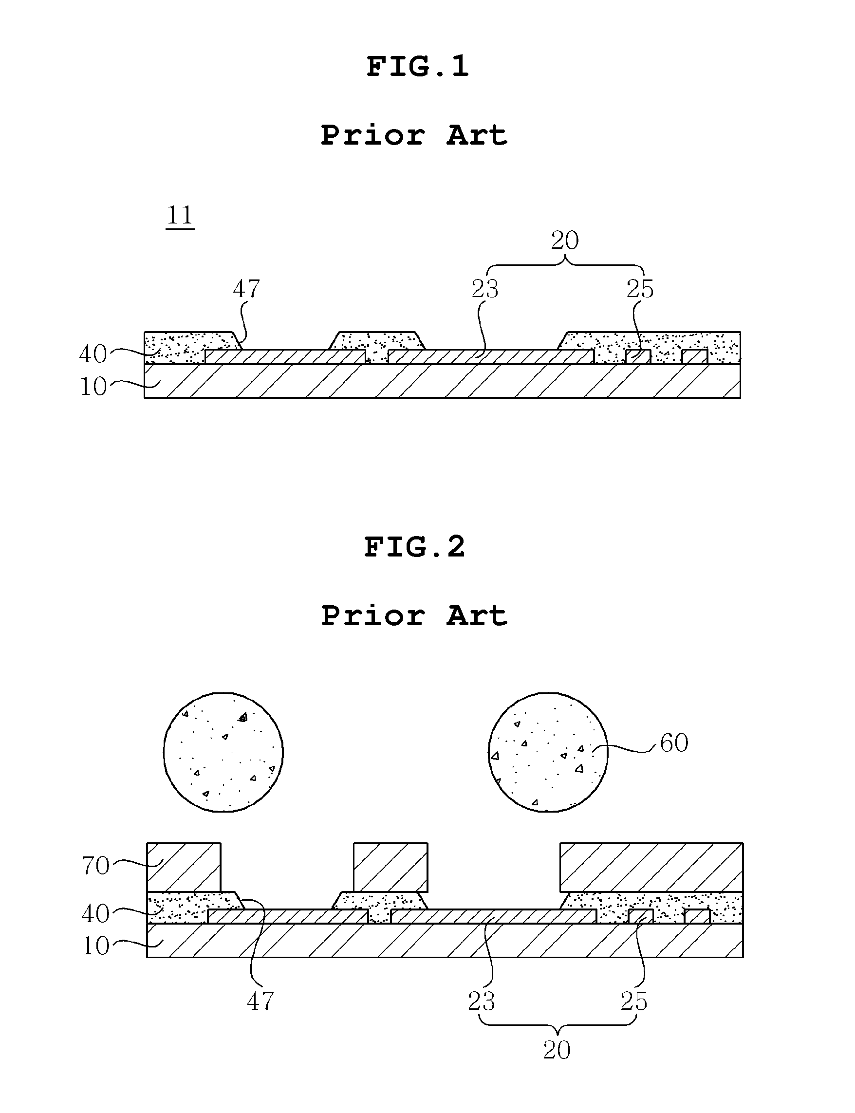
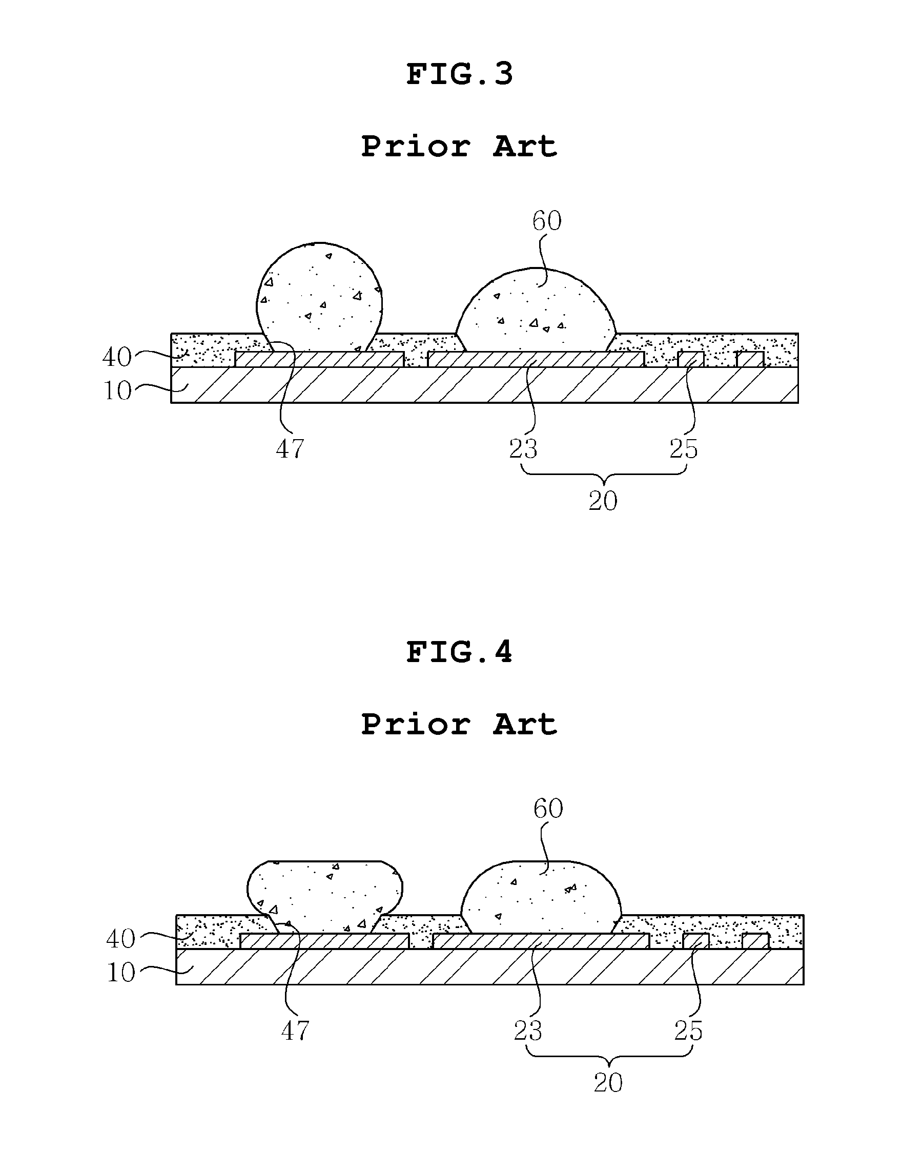
However, because the area on which electronic components of a PCB of a semiconductor package can be mounted is limited, research and development into PCBs having a high degree of integration is ongoing.
Such an additional process may increase the number of processing steps, undesirably reducing manufacturing efficiency, and also the PCB may warp due to the pressure of the press.
In accordance with the trend of increasing the degree of integration and capacity of electronic components, heat generated from electronic components may deteriorate the performance of products.
Thus, in the case where the PCB is conventionally manufactured, procedures of separately manufacturing the heat sink and attaching it to the PCB should be undesirably additionally performed.

Method used


Image

  • Printed circuit board and method of manufacturing the same
  • Printed circuit board and method of manufacturing the same
  • Printed circuit board and method of manufacturing the same

Examples


Embodiment Construction

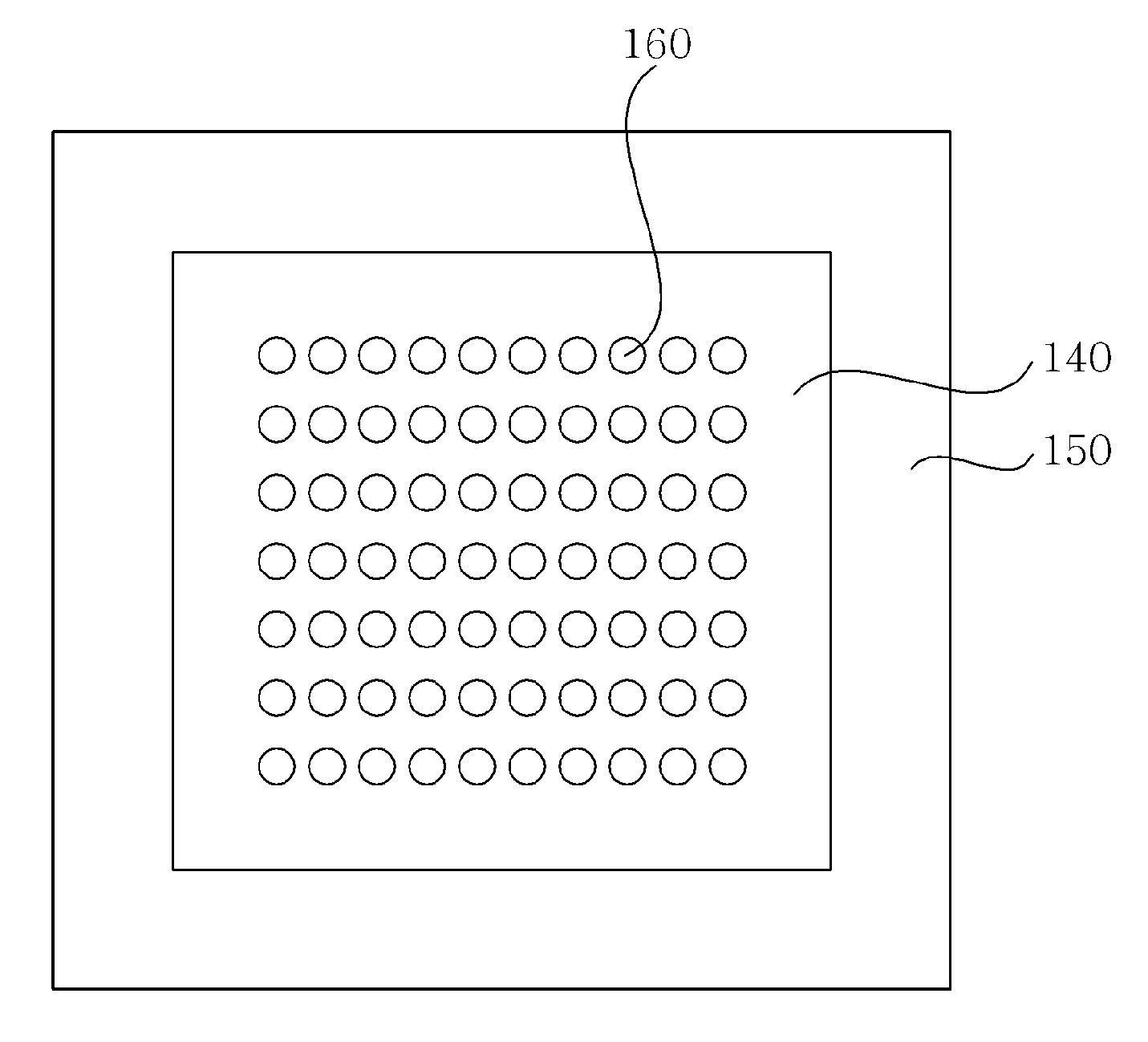
[0029]Hereinafter, embodiments of the present invention will be described in detail while referring to the accompanying drawings. Throughout the drawings, the same reference numerals are used to refer to the same or similar elements. Moreover, descriptions of known techniques, even if they are pertinent to the present invention, are regarded as unnecessary and may be omitted when they would make the characteristics of the invention and the description unclear.

[0030]Furthermore, the terms and words used in the present specification and claims should not be interpreted as being limited to typical meanings or dictionary definitions, but should be interpreted as having meanings and concepts relevant to the technical scope of the present invention based on the rule according to which an inventor can appropriately define the concept implied by the term to best describe the method he or she knows for carrying out the invention.

[0031]PCB

[0032]FIG. 5 is a cross-sectional view showing a PCB a...


PUM

PropertyMeasurementUnit
Diameteraaaaaaaaaa
Heataaaaaaaaaa

Abstract

Disclosed herein is a printed circuit board and a method of manufacturing the same, in which a bump is formed using solder paste printing, and a heat radiation layer is formed using a metal layer used in the course of forming the bump, thus simplifying the formation of the bump, reliably mounting the bump, and improving heat-radiating properties.

Description

CROSS REFERENCE TO RELATED ED APPLICATION[0001]This application claims the benefit of Korean Patent Application No. 10-2010-0123706, filed Dec. 6, 2010, entitled “A method of manufacturing printed circuit board”, which is hereby incorporated by reference in its entirety into this application.BACKGROUND OF THE INVENTION[0002]1. Technical Field[0003]The present invention relates to a printed circuit board (PCB) and a method of manufacturing the same.[0004]2. Description of the Related Art[0005]Along with the recent advancement of electronic technology, there has been an increasing demand for electronic devices which are multi-functionalized and highly dense. However, because the area on which electronic components of a PCB of a semiconductor package can be mounted is limited, research and development into PCBs having a high degree of integration is ongoing. Normally, in order to mount an electronic component on a PCB, pads of a circuit layer are electrically connected with electrodes ...

Claims


Application Information

Patent Timeline
IPC IPC(8): H05K1/02H05K3/10
CPCH05K1/0209H05K3/244H05K3/3452Y10T29/49155H05K3/4007H05K2203/0554H05K2203/0571H05K3/3484H05K3/3485
Inventor KIM, EUNG SOO
Owner SAMSUNG ELECTRO MECHANICS CO LTD
Learn More