Infrared radiation detector

a detector and infrared technology, applied in the field of infrared detectors, can solve the problems of affecting the efficiency of the general vacuum sealed detector, the fitting of the internal face of the cold shield, and the cost of producing such a detector, so as to eliminate stray radiation and reduce the number of the effect of the effect of the number

Active Publication Date: 2012-06-07
DE DETECTEURS INFRAROUGES - SOFRADIR
View PDF5 Cites 9 Cited by
  • Summary
  • Abstract
  • Description
  • Claims
  • Application Information

AI Technical Summary

Benefits of technology

[0015]The present invention aims to obviate the need to use such baffles or at least reduce their number. Nevertheless, it remains within the scope of the above-mentioned type of technology, i.e. technology intended to eliminate stray radiation due to said radiation being reflected out of the field of view of the elementary detectors or photo sites.

Problems solved by technology

The drawback of these baffles is the fact that they are fitted on the internal face of the cold shield by bonding, especially by using an epoxy resin.
Apart from the fact that fixing the baffles involves a time-consuming and awkward operation that makes it more expensive to produce such a detector, experience shows that the epoxy resin used to ensure this bonding causes outgassing which, sooner or later, affects the efficiency of the detector which is generally vacuum sealed.

Method used


Image

  • Infrared radiation detector
  • Infrared radiation detector
  • Infrared radiation detector

Examples


Embodiment Construction

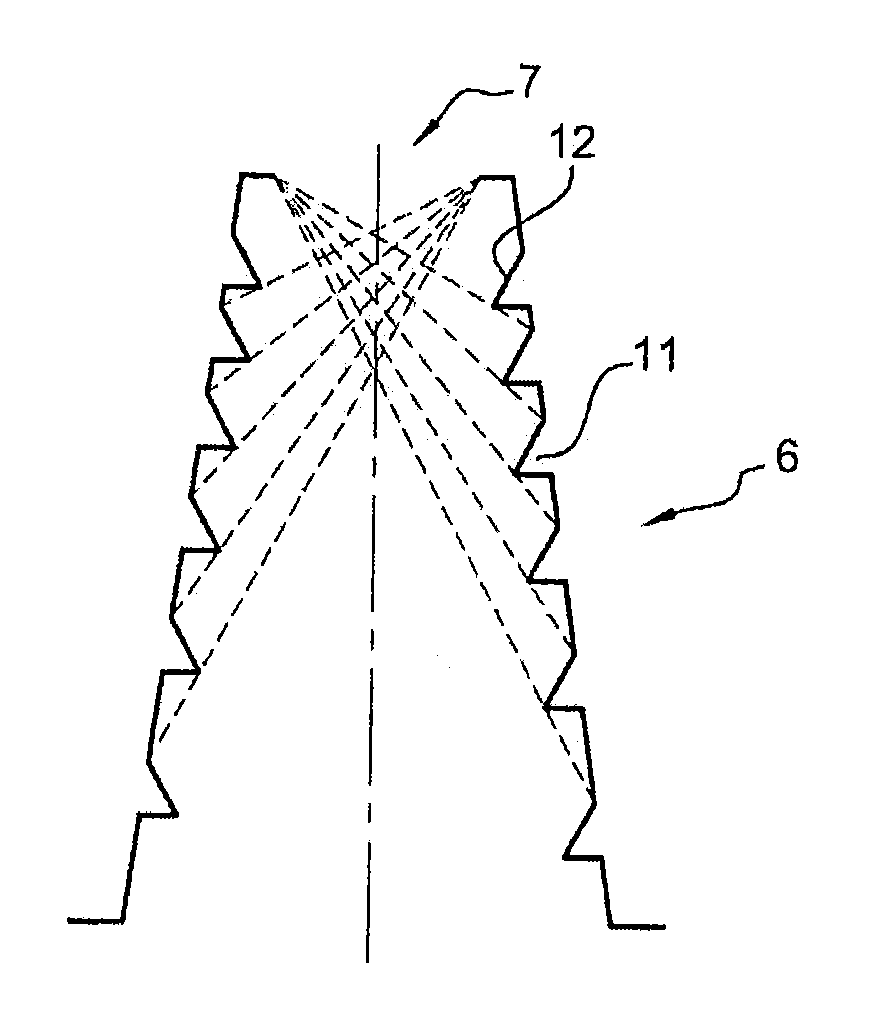
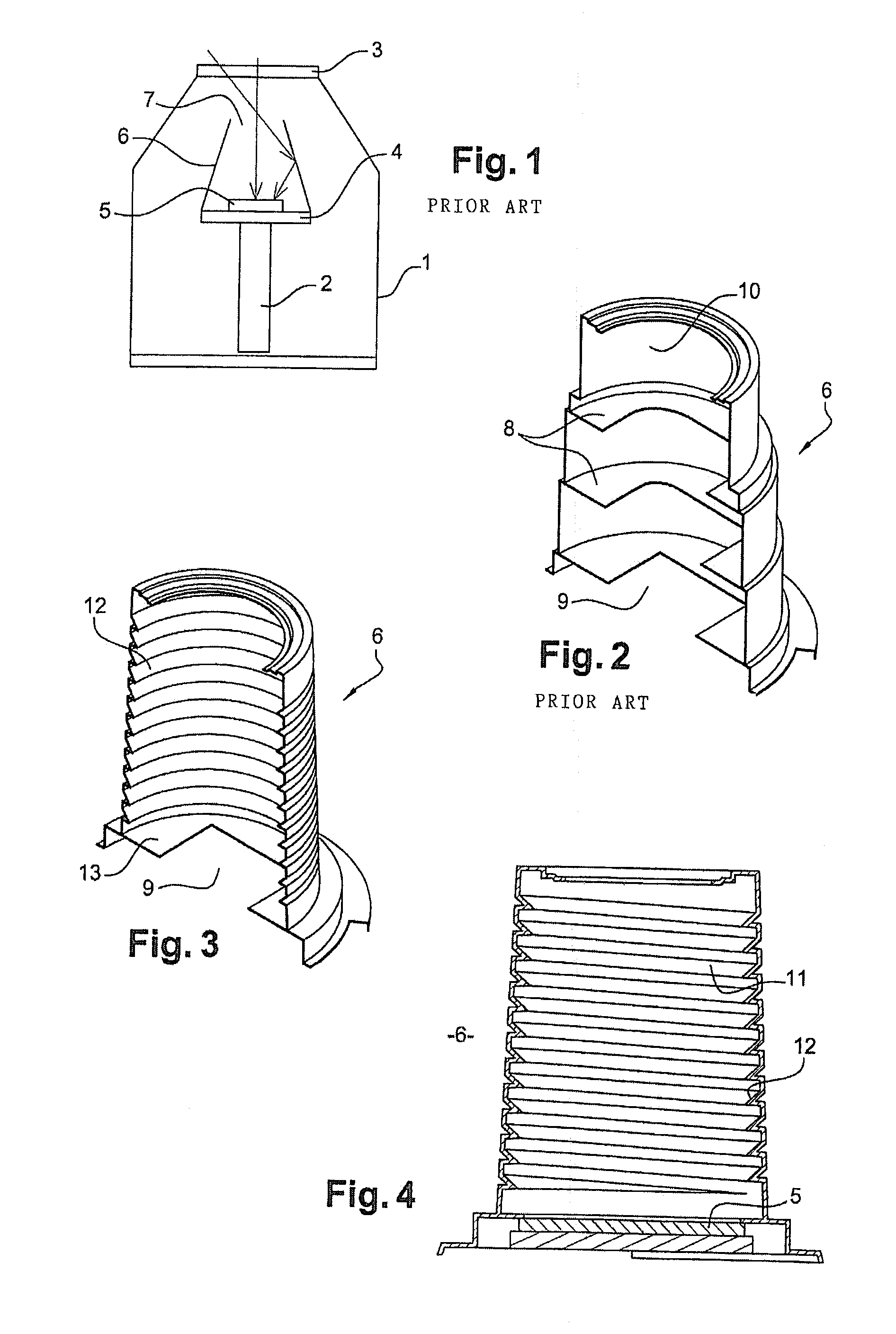
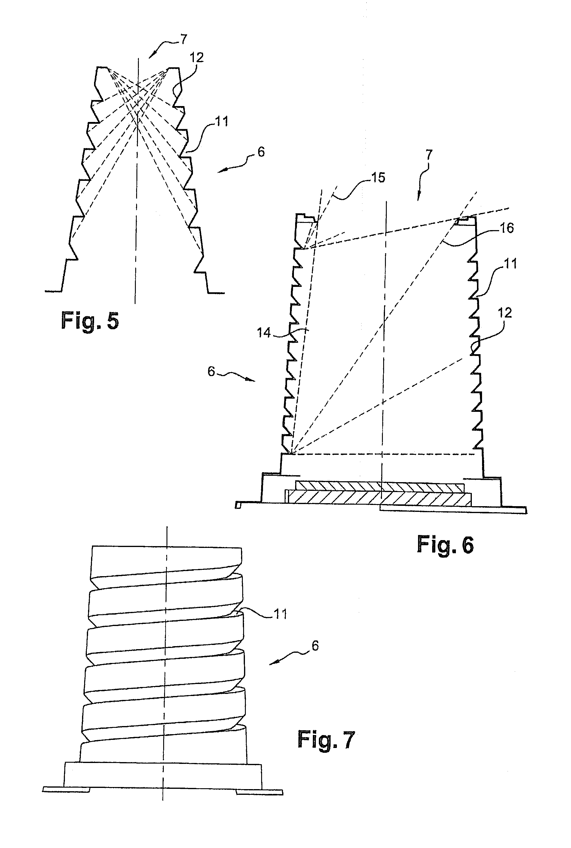
[0035]FIGS. 3, 4 and 6 illustrate the general principle underlying the invention. Thus, cold shield 6 has a circular, tapered cone shape with the frustrum that constitutes the envelope of said shield being defined relative to an axis of revolution that is shown by the dashed lines in FIGS. 5 to 7.

[0036]Cold shield 6 consists of a metal support made of a nickel or copper-based alloy and having a defining side wall which has a particular profile. This particular profile is the result of a helix whose definition axis coincides with the shield's axis of revolution.

[0037]The pith of the helix can be variable, as shown in FIG. 5, in order to reduce the mass of the shield and, consequently, optimize its mechanical strength.

[0038]This pitch can, however, be constant, as shown in FIGS. 3, 4, 6 and 7.

[0039]Even though this is not shown in the drawings, one can even provide two helixes or several helixes in order to optimize the potential reflection density of the particular profile that is ge...


PUM

PropertyMeasurementUnit
transparentaaaaaaaaaa
infrared wavelength rangeaaaaaaaaaa
temperatureaaaaaaaaaa

Abstract

An infrared radiation detector includes: a cryostat having a cold finger ensuring heat exchange with a cold source and a window transparent to infrared radiation to be detected; a mechanically fixed cold plane in heat exchange with the cold finger; a detector unit comprising at least a detector circuit sensitive to the infrared wavelength range to be detected, and in direct or indirect heat exchange with the cold plane; and a mechanically fixed cold shield in heat exchange with the cold plane and limiting stray radiation. The cold shield is rotationally symmetrical. An inside wall of the cold shield has a succession of reliefs distributed in at least one helical pattern. A definition axis of the helical pattern coincides with the axis of revolution of the cold shield.

Description

CROSS REFERENCE TO RELATED APPLICATIONS[0001]This application claims priority of French application No. 1059996 filed on Dec. 2, 2010, the entire contents of which is hereby incorporated by reference herein.FIELD OF THE INVENTION[0002]The invention relates to the field of infrared detectors, more especially those that operate at low temperature, i.e. typically at temperatures from 50 to 200 degrees Kelvin (K).[0003]The operation of such low-temperature infrared detectors is based on the quantum principle and they are generally associated with a vacuum-sealed case (cryostat). The actual detector itself consists of a plurality of unitary or elementary detectors referred to as photo sites, which are associated with a readout circuit, with this assembly, commonly referred to as a “detector unit”, being mechanically fixed and in heat exchange with the cryostat's cold finger so that said detector is kept at the desired temperature.[0004]These devices generally comprise a cold shield which...

Claims


Application Information

Patent Timeline
Patent Type & Authority Applications(United States)
IPC IPC(8): G01J5/02C25D1/00
CPCG01J5/061
Inventor ORLACH, BERTRAND
Owner DE DETECTEURS INFRAROUGES - SOFRADIR
Why Eureka
Try Eureka