
Surface acoustic wave resonator, surface acoustic wave oscillator, and electronic apparatus

a surface acoustic wave and oscillator technology, applied in piezoelectric/electrostrictive/magnetostrictive devices, oscillators, electrical equipment, etc., can solve the problems of increasing the thickness of the electrode film, so as to reduce the frequency deviation reduce the loss of the surface acoustic wave. effect of

Inactive Publication Date: 2012-06-07
SEIKO EPSON CORP
View PDF3 Cites 9 Cited by
  • Summary
  • Abstract
  • Description
  • Claims
  • Application Information

AI Technical Summary

Benefits of technology

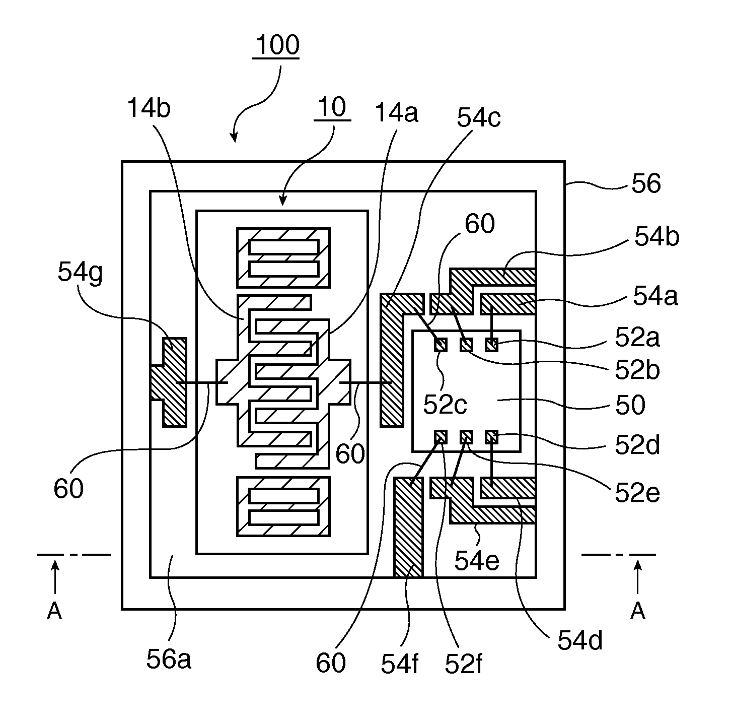
The invention provides a surface acoustic wave resonator that reduces frequency deviation and loss in the resonator. This is achieved by improving the excitation efficiency and reducing fluctuations in the resonance frequency. The invention also includes a quartz crystal substrate with specific electrode fingers and inter-electrode finger grooves, which decrease the loss in the resonator. The invention provides a surface acoustic wave oscillator and electronic apparatus using this resonator that have reduced loss and fluctuation in the resonance frequency.

Problems solved by technology

However, the applicant has found experimentally that on increasing the film thickness of the electrodes, environmental resistance characteristics, such as temporal change characteristics and temperature and shock resistance characteristics, are deteriorated.
Further, when having the improvement of frequency-temperature characteristics as a principal object, it is necessary to increase the electrode film thickness, as described above, and an accompanying deterioration of temporal change characteristics, temperature and shock resistance characteristics, and the like, is unavoidable.
Since this also applies to the Q value, it is difficult to realize a higher Q without increasing the electrode film thickness.

Method used


Image

  • Surface acoustic wave resonator, surface acoustic wave oscillator, and electronic apparatus
  • Surface acoustic wave resonator, surface acoustic wave oscillator, and electronic apparatus
  • Surface acoustic wave resonator, surface acoustic wave oscillator, and electronic apparatus

Examples


first embodiment

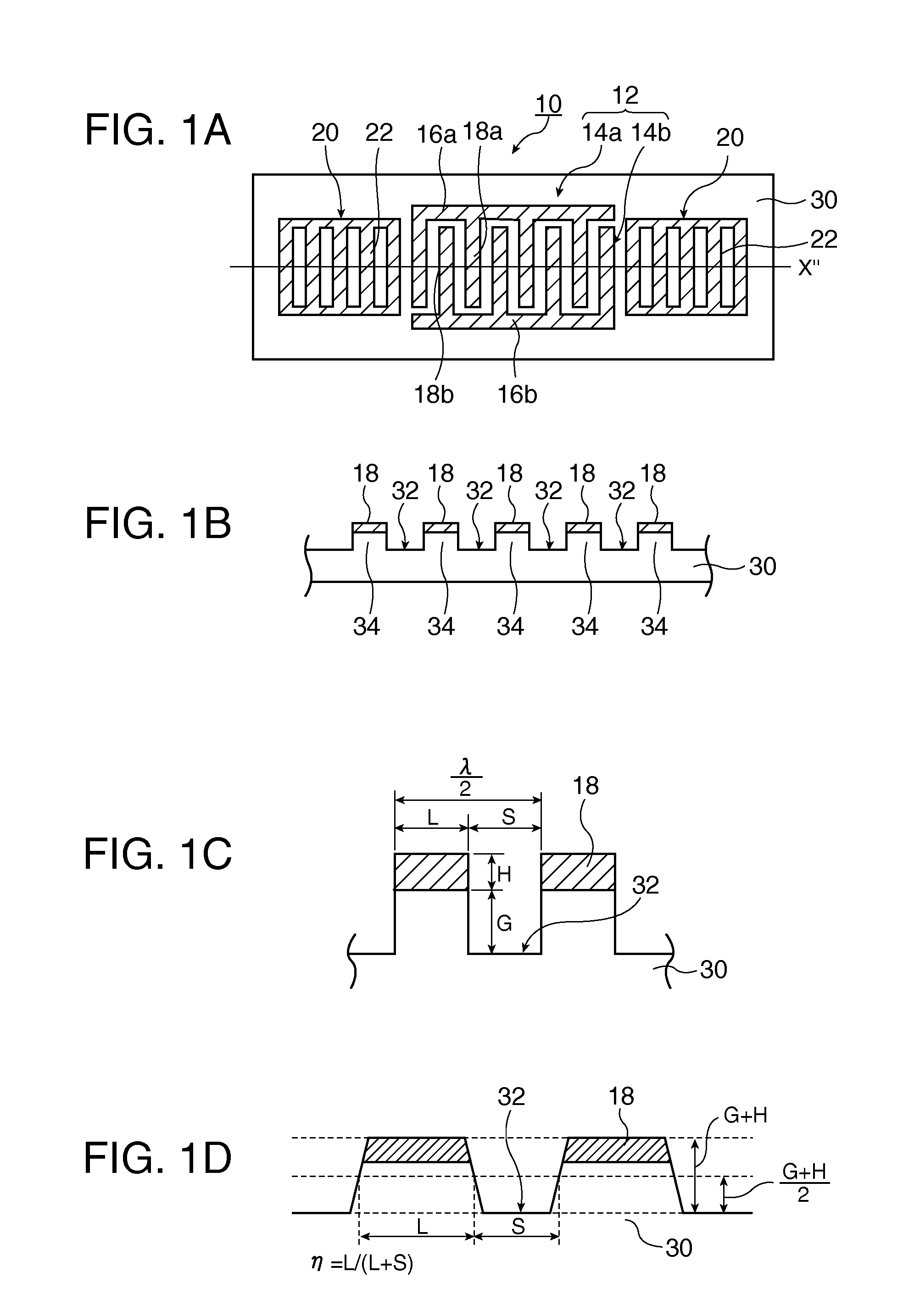
[0109]First, a surface acoustic wave (SAW) resonator according to the invention will be described referring to FIGS. 1A to 1D. In FIGS. 1A to 1D, FIG. 1A is a plan view of the SAW resonator, FIG. 1B is a partial enlarged sectional view, FIG. 1C is an enlarged view for describing details of FIG. 1B, and FIG. 1D is a diagram which, related to the partial enlarged view of FIG. 1C, is for describing an IDT electrode finger line occupation rate η identification method in a case where the cross-sectional shape is not rectangular but trapezoidal, which is a conceivable sectional shape when the SAW resonator according to the embodiment of the invention is manufactured using a photolithography technique and an etching technique. It is appropriate that the line occupation rate η is a proportion occupied by a width L of a value (L+S), wherein a protrusion width L and a width S of a groove 32 are added, at a height from the bottom of the groove 32 which is ½ of (G+H), which is a value where a d...

second embodiment

[0268]In addition, as described above, the inventor has found that a value of the line occupation rate η when a fluctuation amount of the first-order temperature coefficient is the minimum in a case where variations occur in the line occupation rate η and a value of the line occupation rate η where the second-order temperature coefficient β is the minimum (−0.01≦β≦0.01) do not correspond with each other. Therefore, in the second embodiment, a description will be made of a SAW device which can suppress a value of the second-order temperature coefficient β to the above-described range, and can minimize a fluctuation amount of the first-order temperature coefficient which dominantly functions in the frequency-temperature characteristics in the operating temperature range.

[0269]FIGS. 59A to 59D are schematic diagrams of a SAW resonator according to the second embodiment. In FIGS. 59A to 59D, FIG. 59A is a plan view of the SAW resonator according to the second embodiment, FIG. 59B is a p...


PUM


Abstract

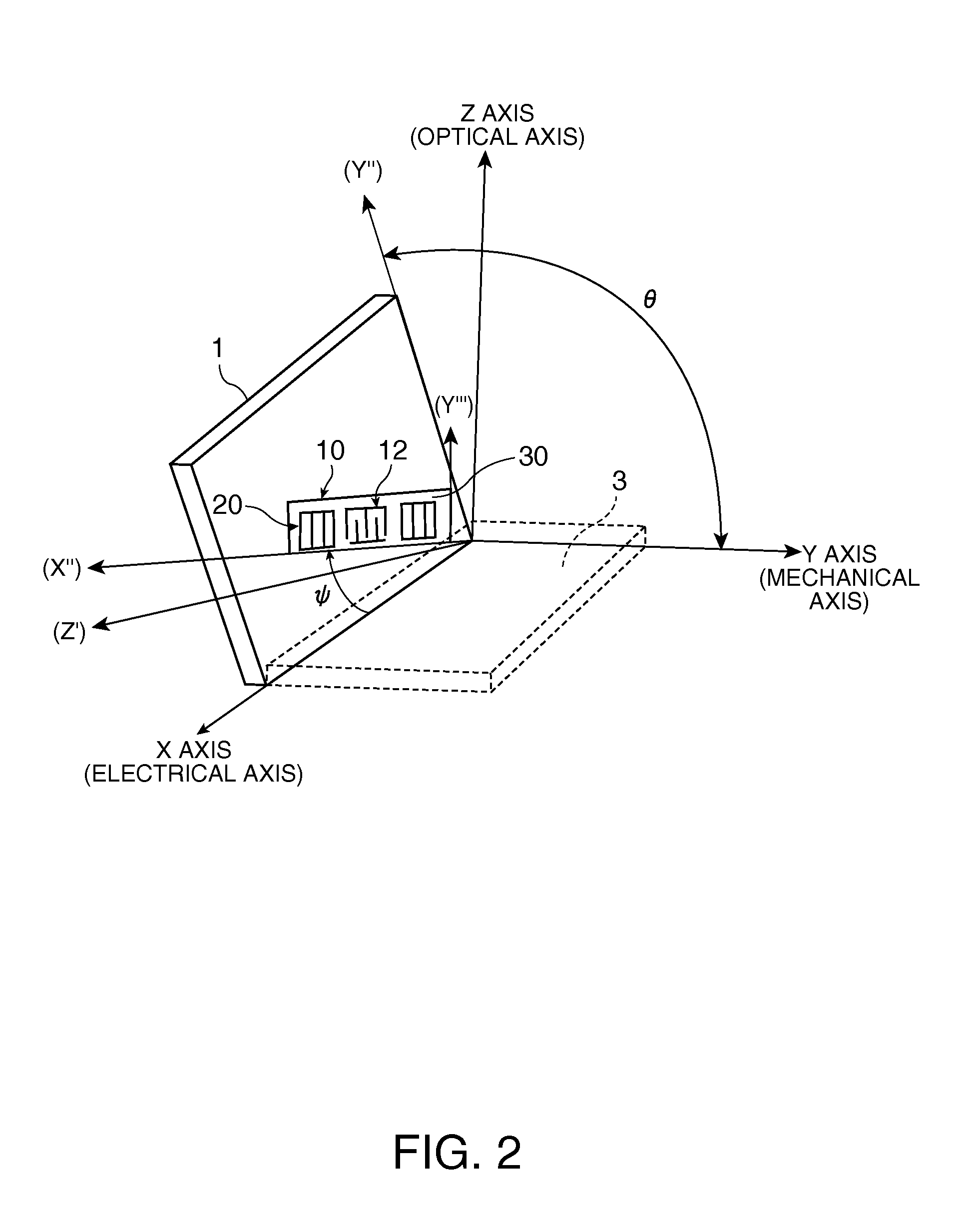
A surface acoustic wave resonator which can realize favorable frequency-temperature characteristics and suppress frequency variations is provided. The surface acoustic wave resonator includes a quartz crystal substrate with Euler angles (−1.5°≦̸&phgr;≦̸1.5°, 117°≦̸&thetas;≦̸142°, and 42.79°≦̸|Ψ|≦̸49.57°), and an IDT that is provided on the quartz crystal substrate, includes a plurality of electrode fingers, and excites a stop band upper end mode surface acoustic wave, wherein inter-electrode finger grooves are provided between the electrode fingers in a plan view, and wherein if a line occupation rate of convex portions of the quartz crystal substrate disposed between the inter-electrode finger grooves is &eegr;g, and a line occupation rate of the electrode fingers disposed on the convex portions is &eegr;e, &eegr;g>&eegr;e and 0.59<&eegr;eff<0.73 are satisfied in a case where an effective line occupation rate &eegr;eff of the IDT is an arithmetic mean of the line occupation rate &eegr;g and the line occupation rate &eegr;e.

Description

BACKGROUND[0001]1. Technical Field[0002]The present invention relates to a surface acoustic wave resonator, a surface acoustic wave oscillator in which the resonator is mounted, and an electronic apparatus, and more particularly to a type of surface acoustic wave resonator where grooves are provided in a substrate surface, and a surface acoustic wave oscillator in which the resonator is mounted.[0003]2. Related Art[0004]In a surface acoustic wave (SAW) device (for example, a SAW resonator), the effect of a SAW stop band, piezoelectric substrate (for example, quartz crystal substrate) cut angle, IDT (interdigital transducer) formation shape, and the like, on changes in frequency-temperature characteristics is considerable.[0005]For example, a configuration exciting each of a SAW stop band upper end mode and lower end mode, the distribution of standing waves in each of the stop band upper end mode and lower end mode, and the like, are disclosed in JP-A-11-214958.[0006]In addition, poi...

Claims


Application Information

Patent Timeline
Patent Type & Authority Applications(United States)
IPC IPC(8): H03B5/30
CPCH03H9/02551H03H9/0542H03H9/1071H01L41/047H03H9/14558H03H9/14594H03H9/14538H03H9/25H03B5/30H03H9/19H10N30/87
Inventor OWAKI, TAKUYAYAMANAKA, KUNIHITOIIZAWA, KEIGOHANO, KENICHI
Owner SEIKO EPSON CORP
Learn More