Ophthalmic apparatus, ophthalmic system, processing apparatus, and blood flow velocity calculation method

a processing apparatus and ophthalmic system technology, applied in the field of blood flow velocity calculation apparatus, can solve the problems of low signal-to-noise ratio, low resolution, and inability to accurately calculate the blood flow velocity, and achieve the effect of accurately calculating the blood flow velocity

Inactive Publication Date: 2012-06-07
CANON KK
View PDF4 Cites 20 Cited by
  • Summary
  • Abstract
  • Description
  • Claims
  • Application Information

AI Technical Summary

Benefits of technology

[0015]According to the above aspects of the present invention, it is possible to utilize the scanning period (the scanning speed and the scanning interval of the scanning unit) required for the scanning unit to scan the distance from the position corresponding to the first position in the second image to the second position as well as the time required for acquiring one planar image. In this way, since the period from when the scanning unit acquires the position (the first position) of the blood cell in the first planar image to when the scanning unit acquires the position (the second position) of the blood cell in the second planar image can be utilized, it is possible to accurately calculate the blood flow velocity.

Problems solved by technology

However, with the increase in the beam diameter of the measurement beam, the acquired planar image of the retina has an issue of a low signal-to-noise (SN) ratio and a low resolution due to an aberration of a subject's eye.
Accordingly, the technique discussed in the above document cannot accurately calculate the blood flow velocity.

Method used


Image

  • Ophthalmic apparatus, ophthalmic system, processing apparatus, and blood flow velocity calculation method
  • Ophthalmic apparatus, ophthalmic system, processing apparatus, and blood flow velocity calculation method
  • Ophthalmic apparatus, ophthalmic system, processing apparatus, and blood flow velocity calculation method

Examples


Embodiment Construction

[0023]Various exemplary embodiments, features, and aspects of the invention will be described in detail below with reference to the drawings.

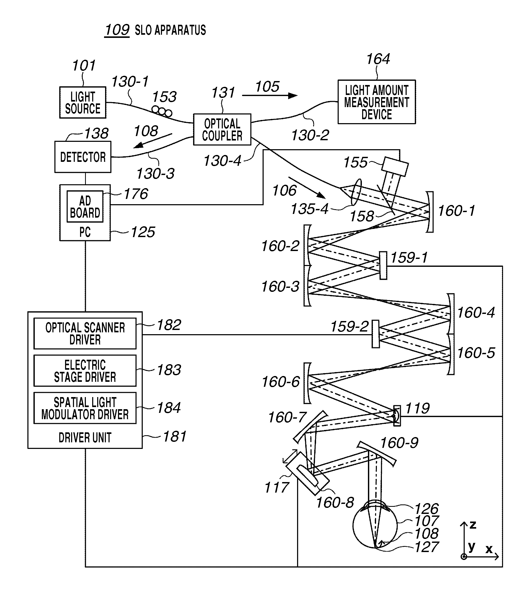
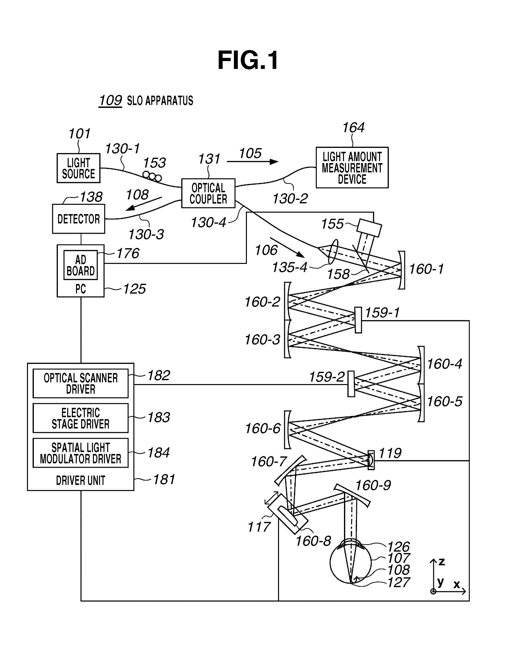
[0024]A blood flow velocity calculation apparatus (an ophthalmic apparatus or an ophthalmic system) according to the present invention includes an irradiation unit (also referred to as an illumination optical system) that irradiates a subject's eye with a measurement beam scanned by a scanning unit (for example, an XY scanner 119). Further, the blood flow velocity calculation apparatus includes an acquisition unit (for example, a personal computer (PC) 125) that acquires an image (for example, a planar image) of the subject's eye based on a return beam, from the subject's eye, of the measurement beam irradiated by the irradiation unit.

[0025]Moreover, the blood flow velocity calculation apparatus includes a calculation unit (for example, the PC 125) that calculates the blood flow velocity of the subject's eye based on a displacement between a po...


PUM


Abstract

An ophthalmic apparatus includes an irradiation unit configured to irradiate a subject's eye with a measurement beam scanned by a scanning unit, an acquisition unit configured to acquire an image of the subject's eye based on a return beam returned from the subject's eye, of the measurement beam irradiated by the irradiation unit, and a calculation unit configured to calculate a blood flow velocity of the subject's eye based on a displacement between a position of a blood cell in a first image obtained by the acquisition unit and a position of the blood cell in a second image obtained by the acquisition unit at a different time from the first image and on a difference between time when an image of the blood cell in the first image is obtained and time when an image of the blood cell in the second image is obtained.

Description

BACKGROUND OF THE INVENTION[0001]1. Field of the Invention[0002]The present invention relates a blood flow velocity calculation apparatus and a method thereof, and more particularly, to an ophthalmic apparatus, an ophthalmic system, a processing apparatus, and a blood flow velocity calculation method used for an ophthalmic care.[0003]2. Description of the Related Art[0004]A scanning laser ophthalmoscope (SLO) which is an ophthalmic apparatus using the principle of a confocal laser microscope is a device that performs raster scan on an eye fundus with a laser as a measurement beam to obtain high resolution planar images at high speed from an intensity of return beam of the measurement beam.[0005]Hereinafter, the device that captures such a planar image will be referred to as an SLO apparatus.[0006]In recent years, the SLO apparatus has been able to acquire a planar image of a retina with an improved horizontal resolution by increasing a beam diameter of a measurement beam. However, w...

Claims


Application Information

Patent Timeline
Patent Type & Authority Applications(United States)
IPC IPC(8): A61B3/14
CPCA61B3/12A61B3/1233A61B3/1025A61B3/14A61B3/1241A61B5/026G01B9/02
Inventor HIROSE, FUTOSHIIMAMURA, HIROSHI
Owner CANON KK
Why Eureka
Try Eureka