Method and apparatus for calculating packet arrival time interval

a packet arrival time and packet technology, applied in the field of mobile communication, can solve the problems of data congestion, consuming a lot of operation resources, and failing to achieve the traffic policing effect, and achieve the effect of large storage spa

Active Publication Date: 2012-06-07
ZTE CORP
View PDF12 Cites 6 Cited by
  • Summary
  • Abstract
  • Description
  • Claims
  • Application Information

AI Technical Summary

Benefits of technology

[0010]In view of this, the present invention provides an improved solution for calculating packet arrival time interval, in order to solve the problem in the conventional art t

Problems solved by technology

Since the packet arrival time interval in data network is in random, the burst data traffic which has exceeded the processable capacity of a network node may lead to data congestion when passing through the network node.
If the constant interval is larger, dramatic fluctuation may be caused in the packet passing rate, thus failing to achieve the traffic policing effect.
If the constant interval is small herein, the system will need to perform adding the tokens frequently, which can consume a lot of operation resources.
When using this method, if the arrival time interval of a packet is too long, the timer will overflow, thus leading to an error i

Method used


Image

  • Method and apparatus for calculating packet arrival time interval
  • Method and apparatus for calculating packet arrival time interval
  • Method and apparatus for calculating packet arrival time interval

Examples


embodiment i

[0049]This Embodiment is explained by means of the procedure of updating the flag bit recorded in the internal RAM and the arrival time of previous packet recorded in the external RAM when the current packet arrives.

[0050]FIG. 4 is the flowchart of this Embodiment. As shown in FIG. 4, the procedure of updating the flag bit recorded in the internal RAM and the arrival time of previous packet recorded in the external RAM when the current packet arrives mainly comprises the following steps.

[0051]Step S401, when the current packet arrives, the value of the current system timer is written into the external RAM with the serial number of the flow to which the packet belongs as the address.

[0052]Step S403, the flag bit of the internal dual-port RAM is set as 1 with the serial number of the flow to which the packet belongs as the address. In the above steps, the order of Step S401 or Step S403 is not limited. At this time, the packet arrival time updating ends.

embodiment ii

[0053]This Embodiment describes the procedure of scanning the flag bit of the arrival time of previous packet of each flow recorded in the internal RAM.

[0054]FIG. 5 is the flowchart of this Embodiment. As shown in FIG. 5, in this embodiment, the procedure of scanning and updating the flag bit of the arrival time of previous packet of each flow recorded in the internal RAM mainly comprises the following steps.

[0055]Step S501: after the flag bit scanning and updating procedure begins, it is judged whether the value of the system timer is 0, wherein if the judgment result is yes, Step S502 is performed, otherwise, the judgment is continued.

[0056]Step S502: when the counting value of the system timer is 0, a new round of flag bit scanning and updating is started up and the index number of the current scanned flow is cleared to 0.

[0057]Step S503: the flag bit of the current scanned flow is read with the index number of the current scanned flow as the address.

[0058]Step S504: if the read ...

embodiment iii

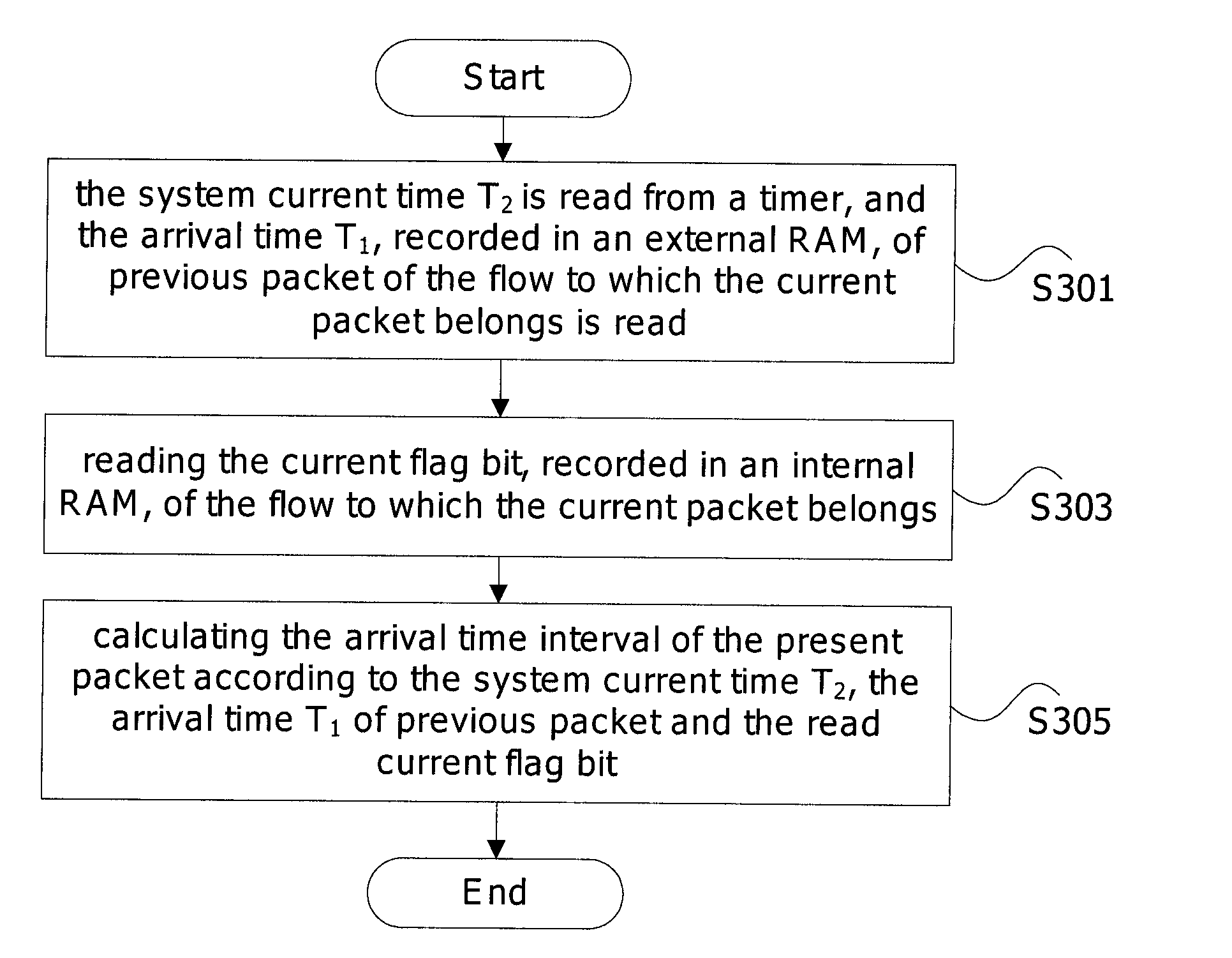
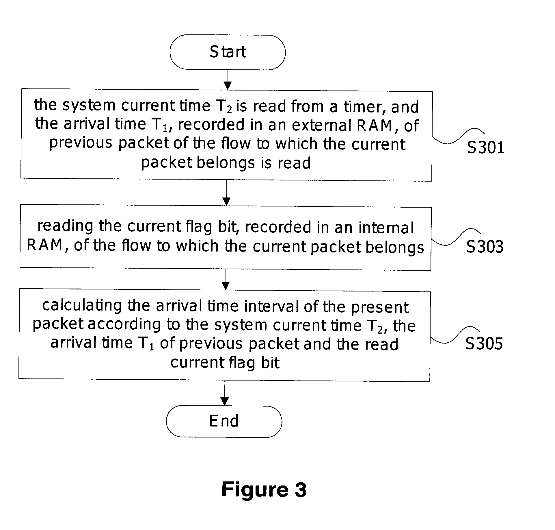
[0062]In this Embodiment, the procedure of calculating the arrival time interval of the present packet after the current packet arrives is described.

[0063]FIG. 6 is the flowchart of this Embodiment. As shown in FIG. 6, in this Embodiment, the procedure of calculating the arrival time interval of the present packet when the current packet arrives mainly comprises the following steps.

[0064]Step S601, recording the arrival time T2 of current packet; reading the external RAM to read out the arrival time T1 of previous packet of the flow to which the packet belongs; and reading the internal dual-port RAM to read out the current flag bit of the flow to which the packet belongs.

[0065]Step S602, judging the read flat bit, wherein if the flag bit is 2′b01 (namely ‘01’ occupies 2 bits), then the present packet arrival time interval at present time is (T2−T1); if the flag bit is 2′b10 and T2≧T1, the token bucket has overflowed and shall be filled up directly; if the flag bit is 2′b10 and T21, ...


PUM


Abstract

A method and an apparatus for calculating packet arrival time interval are provided by the present invention. In the above-mentioned method, when the current packet arrives, system current time T2 is read from a timer, and the arrival time T1, recorded in an external RAM, of previous packet of the flow to which the current packet belongs is read (301), wherein the timer implements a cycle timing with a period of preset time period Tmax, the preset time period Tmax is larger than or equal to the time for filling the maximum depth of the token bucket of the flow at the minimum token injection rate; a current flag bit, recorded in an internal RAM, of the flow to which the current packet belongs is read (303), wherein the current flag bit is used for indicating the number of cycles of the timer between the system current time T2 and the arrival time T1 of previous packet; and the arrival time interval of the present packet is calculated according to the system current time T2, the arrival time T1 of previous packet and the current flag bit (305). Application of the present invention can reduce the consumption of the internal RAM and improve the operability for realizing by the hardware chips.

Description

CROSS-REFERENCE TO RELATED APPLICATIONS[0001]This application is the U.S. National Stage of International Patent Application No. PCT / CN2009 / 074097 filed on Sep. 22, 2009, which claims priority to Chinese Patent Application Number 200910164032.4 filed on Aug. 4, 2009, the disclosures of which are hereby incorporated by reference in their entireties.FIELD OF THE INVENTION [0002]The present invention relates to mobile communication field, and in particular to a method and an apparatus for calculating packet arrival time interval.BACKGROUND OF THE INVENTION[0003]Since the packet arrival time interval in data network is in random, the burst data traffic which has exceeded the processable capacity of a network node may lead to data congestion when passing through the network node.[0004]Currently, to avoid the impact of the burst data traffic on communications, the packet traffic policing method based on token bucket is generally used. FIG. 1 is the schematic diagram of the principle of th...

Claims


Application Information

Patent Timeline
IPC IPC(8): H04L12/26
CPCH04W56/005H04B17/20H04L47/215
Inventor XIAO, JIEWU, BIANWU, FENGBOYU, CHEN
Owner ZTE CORP
Why Eureka
Try Eureka