
Photonic band gap fibers using a jacket with a depressed softening temperature

Active Publication Date: 2012-06-07
THE UNITED STATES OF AMERICA AS REPRESENTED BY THE SECRETARY OF THE NAVY
View PDF7 Cites 14 Cited by
  • Summary
  • Abstract
  • Description
  • Claims
  • Application Information

AI Technical Summary

Benefits of technology

[0006]The aforementioned problems are overcome in the present invention which provides a photonic bad gap fiber and/or fiber preform with a central structured region comprising a first non-silica based glass and a jacket comprising a second non-silica based glass surrounding the central structured region, where the Littleton softening temperature, i.e. the temperature at which a glass has a viscosity of 107.6 poises, of the second glass is at least

Problems solved by technology

This assembly process inevitably introduces voids between the central region and the outer jacket tube.
These voids can be similarly sized to the intended holes in the structured region of the fiber preform, or even larger, and run the entire length of the fiber preform, therefore making fiberization difficult.
However, this method does not work for non silica specialty glasses, especially non-oxides and chalcogenides, due to their low softening temperatures and higher vapor pressures.
Specialty glasses tend to be more fragile and, therefore, difficult to make and handle the microstructured fiber preforms.

Method used


Image

  • Photonic band gap fibers using a jacket with a depressed softening temperature
  • Photonic band gap fibers using a jacket with a depressed softening temperature
  • Photonic band gap fibers using a jacket with a depressed softening temperature

Examples


Embodiment Construction

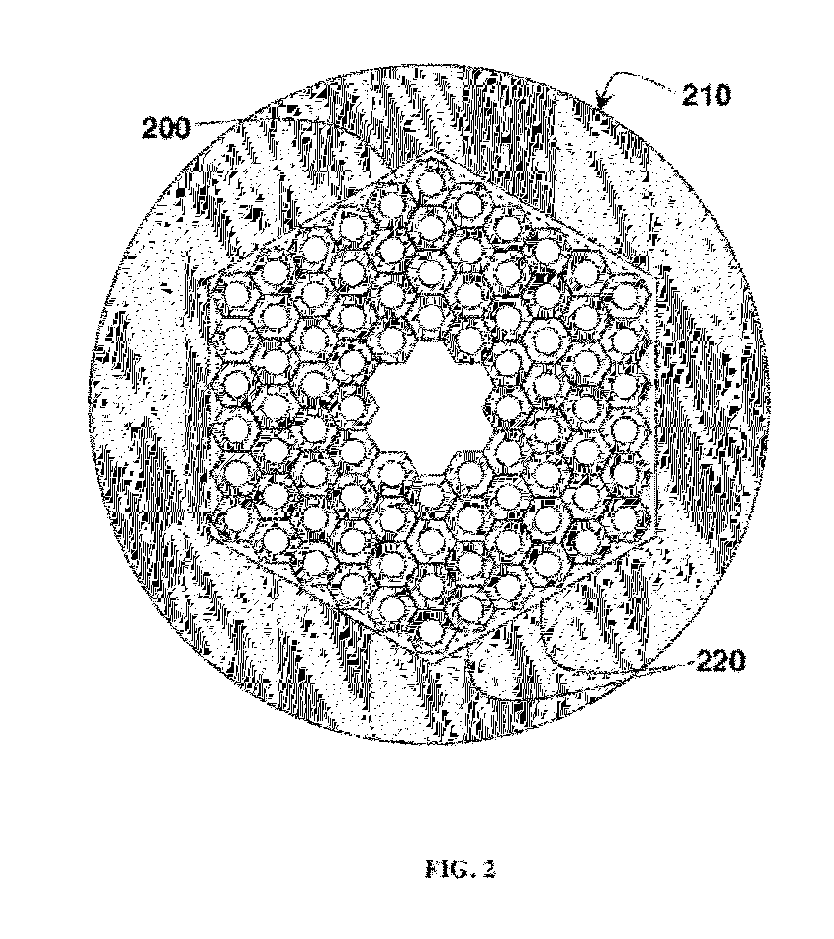
[0014]According to the present invention, a structured photonic band gap fiber and / or fiber preform uses at least two different compositions of non-silica based specialty glass in the same fiber and / or fiber preform to reduce or eliminate the interstitial voids in the structured fiber preform and / or the fiber. As shown in FIG. 2, the structured central region 200 of the fiber preform comprises a specialty non-silica based glass whose composition is chosen such that it has the desired optical properties for band gap guidance at the wavelength of interest. The central structured region 200 of the fiber preform has open holes that run the length of the fiber preform in predetermined positions. The structured central region 200 is surrounded by a jacket 210 comprising a different composition of a non-silica based glass than the structured central region 200. The jacket 210 may be a jacket tube. The jacket 210 has a single open hole which runs the length of the fiber preform and can be r...


PUM

PropertyMeasurementUnit
Temperatureaaaaaaaaaa
Viscosityaaaaaaaaaa
Temperatureaaaaaaaaaa

Abstract

The present invention is generally directed to a photonic bad gap fiber and / or fiber preform with a central structured region comprising a first non-silica based glass and a jacket comprising a second non-silica based glass surrounding the central structured region, where the Littleton softening temperature of the second glass is at least one but no more than ten degrees Celsius lower than the Littleton softening temperature of the first glass, or where the base ten logarithm of the glass viscosity in poise of the second glass is at least 0.01 but no more than 2 lower than the base ten logarithm of the glass viscosity in poise of the first glass at a fiber draw temperature. Also disclosed is a method of making a photonic bad gap fiber and / or fiber preform.

Description

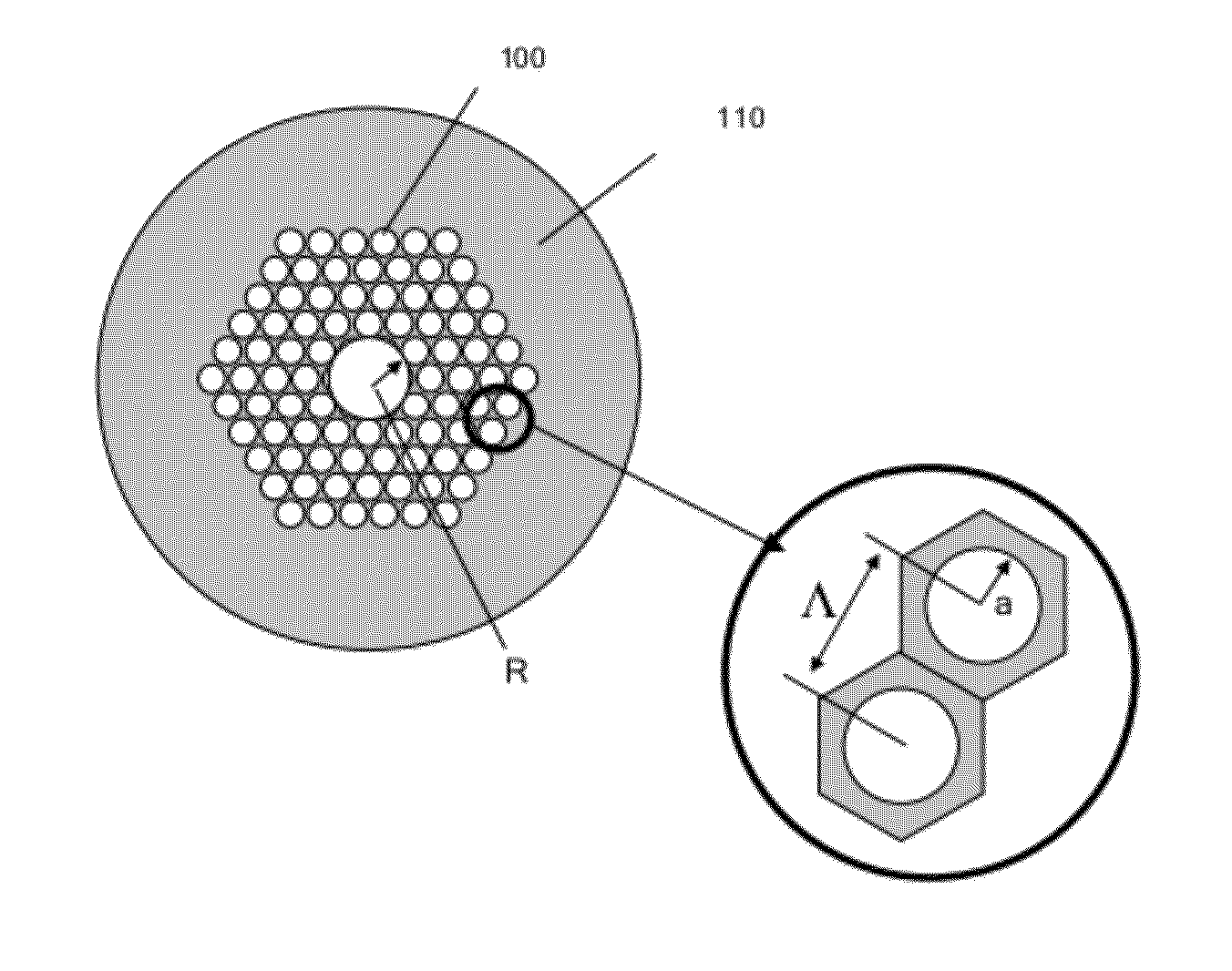
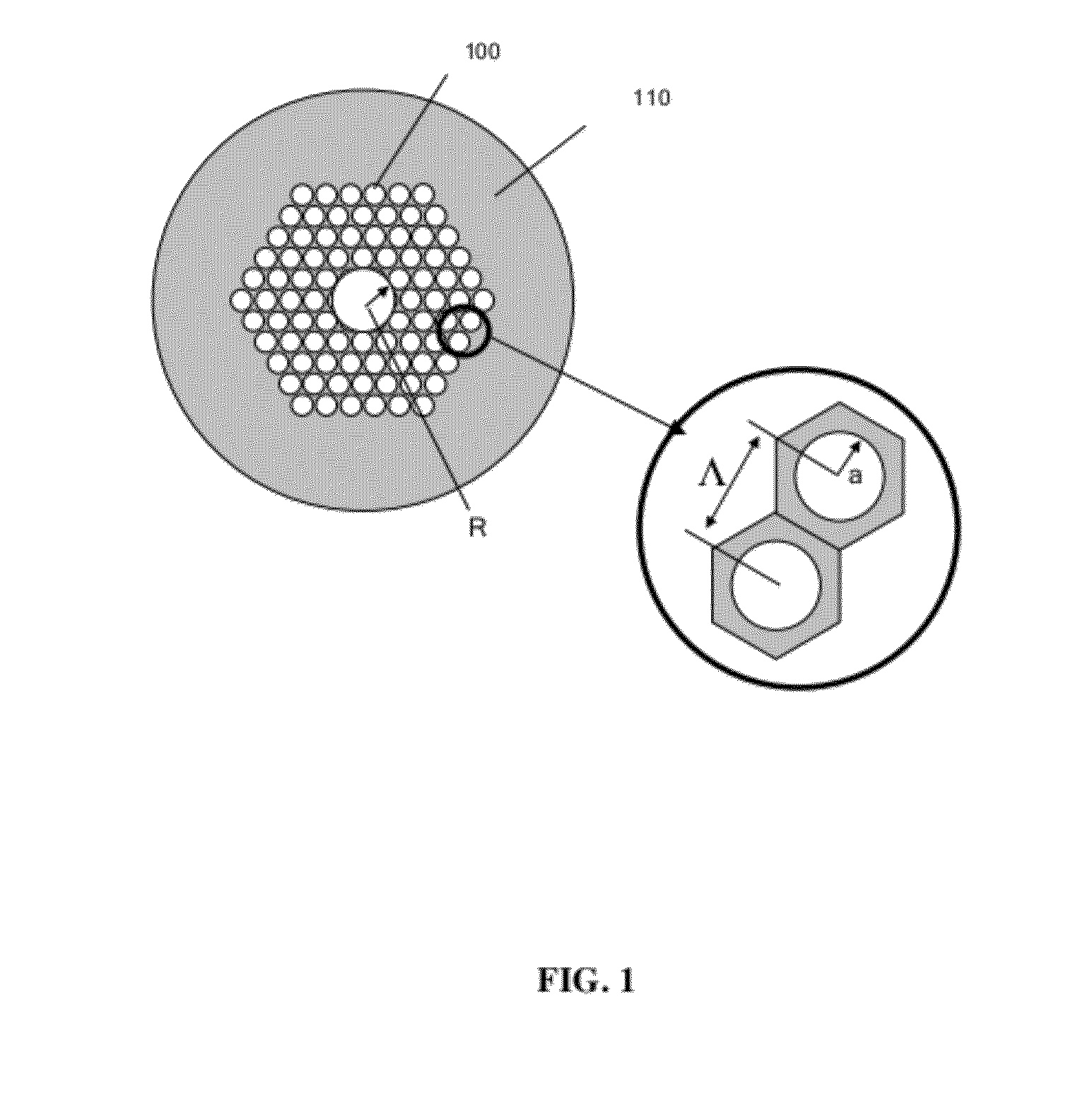
FIELD OF THE INVENTION[0001]The present invention relates generally to photonic band gap fibers, and more specifically to non-silica glass based photonic band gap fibers.BACKGROUND OF THE INVENTION[0002]Hollow core photonic band gap (HC-PBG) fibers have been fabricated from silica glass and reported in the literature. See, e.g., Cregan et al., “Single-mode photonic bad gap guidance of light in air,”Science, 285(5433), 1537-1539 (1999); Barkou et al., “Silica-air photonic crystal fiber design that permits waveguiding by a true photonic bandgap effect.”Optics Letters, 24(1), 46-48 (1999); and Venkataraman et al., “Low loss (13 dB / km) air core photonic band-gap fibre,” ECOC, Postdeadline Paper PD1. 1, September, 2002, all of which are incorporated herein by reference. FIG. 1 shows a schematic of the cross-section of a HC-PBG fiber. The periodic layered structure of air holes 100 and glass 110 creates a photonic band gap that prevents light from propagating in the structured region (ana...

Claims


Application Information

Patent Timeline
IPC IPC(8): G02B6/032C03B37/075
CPCC03B37/0122C03B37/0279C03B2201/60C03B2201/80C03B2201/84G02B6/02347C03B2203/14C03B2203/222C03B2203/42G02B6/02328C03B2201/86G02B6/02338
Inventor GIBSON, DANIEL J.SANGHERA, JASBINDER S.KUNG, FREDERIC H.AGGARWAL, ISHWAR D.
Owner THE UNITED STATES OF AMERICA AS REPRESENTED BY THE SECRETARY OF THE NAVY
Learn More