Oil pump system for automatic transmission

a pump system and automatic transmission technology, applied in the direction of positive displacement liquid engines, machines/engines, gearing details, etc., can solve the problems of power loss, excessive load applied to the pump, durability deterioration, etc., to prevent excessive power loss and durability deterioration

Active Publication Date: 2012-06-07
HYUNDAI MOTOR CO LTD
View PDF2 Cites 33 Cited by
  • Summary
  • Abstract
  • Description
  • Claims
  • Application Information

AI Technical Summary

Benefits of technology

[0010]Various aspects of the present invention provide for a hydraulic pump system for an automatic transmission having advantages of preventing excessive power loss and durability deterioration.
[0011]Various aspects of the present invention provide for a hydraulic pump system for an automatic transmission having advantages of pumping entire oil flux by a low pressure portion and discharging a necessary oil flux by a high pressure portion to reduce noise and pressure vibration of a hydraulic pump.
[0015]A low pressure regulating valve that is connected to the low pressure passage may set the first hydraulic pressure to return remained oil to the oil fan.
[0022]In various embodiments of the present invention as described above, the first hydraulic pump discharges an entire oil flux based on a low pressure and the second hydraulic pump discharges a necessary high pressure such that an excessive load is not applied to the hydraulic pump to prevent a power loss and durability thereof. Also, noise and pressure vibration of the hydraulic pump can be reduced.

Problems solved by technology

However, the hydraulic pump pumps entire oil flux base on the high pressure portion and therefore an excessive load is applied to the pump.
A durability is deteriorated, a power is lost, and noise and pressure vibration are generated thereby.

Method used


Image

  • Oil pump system for automatic transmission
  • Oil pump system for automatic transmission
  • Oil pump system for automatic transmission

Examples


Embodiment Construction

[0027]Reference will now be made in detail to various embodiments of the present invention(s), examples of which are illustrated in the accompanying drawings and described below. While the invention(s) will be described in conjunction with exemplary embodiments, it will be understood that present description is not intended to limit the invention(s) to those exemplary embodiments. On the contrary, the invention(s) is / are intended to cover not only the exemplary embodiments, but also various alternatives, modifications, equivalents and other embodiments, which may be included within the spirit and scope of the invention as defined by the appended claims.

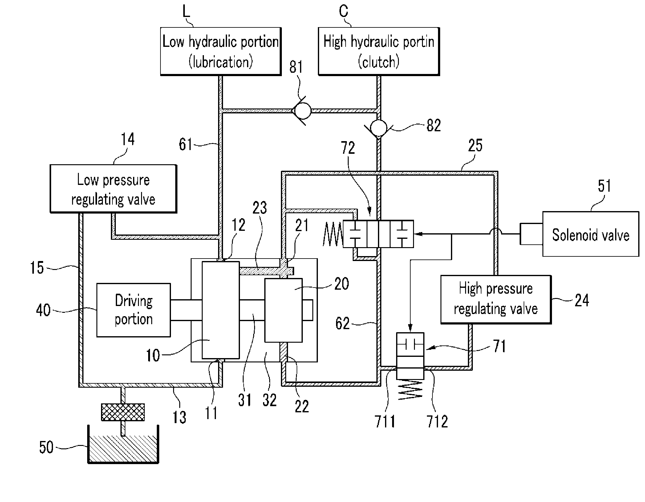
[0028]FIG. 1 is a hydraulic circuit diagram showing a condition that a high pressure portion of a hydraulic pump system for an automatic transmission (hereinafter, it is referred to as “hydraulic pump system”) is operated according to various embodiments of the present invention. That is, the hydraulic pump system supplies a high pres...


PUM


Abstract

A hydraulic pump system for an automatic transmission has the advantages of preventing excessive power loss and durability deterioration. The hydraulic pump system may include a first hydraulic pump that generates a first hydraulic pressure to supply a low pressure portion with the first hydraulic pump, a second hydraulic pump that receives the first hydraulic pressure to generate a second hydraulic pressure higher than the first hydraulic pressure and supplies a high pressure portion with the second hydraulic pressure, and a drive portion that rotates a drive shaft that integrally connects the first hydraulic pump with the second hydraulic pump.

Description

CROSS-REFERENCE TO RELATED APPLICATION[0001]This application claims priority to and the benefit of Korean Patent Application No. 10-2010-0123019 filed Dec. 3, 2010, the entire contents of which application is incorporated herein for all purposes by this reference.BACKGROUND OF INVENTION[0002]1. Field of Invention[0003]The present invention relates to a hydraulic pump system for an automatic transmission that is configured to minimize a power loss caused by a hydraulic pump.[0004]2. Description of Related Art[0005]For example, a hydraulic pump that is operated by an engine has a suction hole that is connected to an oil fan to supply a discharge hole with pumped oil in a hydraulic pump system for an automatic transmission.[0006]The discharge hole is connected to a high pressure portion (for example, clutch) through a high pressure passage, and a high pressure regulating valve is disposed on a high pressure passage. The high pressure passage supplies a high hydraulic pressure to the hi...

Claims


Application Information

Patent Timeline
Patent Type & Authority Applications(United States)
IPC IPC(8): F04B23/04F04B17/00
CPCY10T477/69395F16H2061/0037F16H61/0025F16H57/0441
Inventor HWANG, JIN YOUNG
Owner HYUNDAI MOTOR CO LTD
Why Eureka
Try Eureka