Ald coating system

a technology of coating system and evaporation layer, which is applied in the direction of vacuum evaporation coating, coating, chemical vapor deposition coating, etc., can solve the problems of surface visible sign, physical and chemical properties can be compromised, performance degradation and eventual failur

Inactive Publication Date: 2012-06-07
ULTRATECH INT INC
View PDF11 Cites 58 Cited by
  • Summary
  • Abstract
  • Description
  • Claims
  • Application Information

AI Technical Summary

Problems solved by technology

When mixed precursors contaminate a substrate coating surface its physical and chemical properties can be compromised with very little visible sign that the surface is contaminated.
Surface contamination resulting from contact with mixed precursor usually leads to performance degradation and eventual failure.
One problem with the distribution manifold disclosed by Levy et al. is that the separation distance D between the coating surface and the output face of the distribution manifold is necessary small.
However Applicants have found that the small separation distance D is not practical in a typical coating application because many substrate materials being coated have, surface variations that exceed 25 μm; the separation distance recommended in Levy et al.
In particular variations in substrate thickness, in the geometry of elements supporting the substrate and in the manifold itself can easily exceed 25 μm with the result that during movement of the coating surface past the distribution manifold at the desired coating velocity contact between the coating surface and the distribution manifold can easily occur resulting undesirable coating surface and substrate damage.
While Levy et al. disclose a system for ALD coating at atmospheric pressure, the system disclosed by Levy et al. requires a small separation distance (25 μm or less) between the substrate coating surface and the lower ends of the partitions used to form gas flow channels and a 25 μm, separation distance is impractical for many applications that require more variability in the separation distance.
One problem is that the thickness of the some materials being coated can vary more than 25 μm.
Another problem is that material stretching and position variations due to transport drive forces can cause the separation distance to vary more than 25 μm as the material is advanced past the gas distribution manifold.

Method used


Image

  • Ald coating system
  • Ald coating system
  • Ald coating system

Examples


example 1

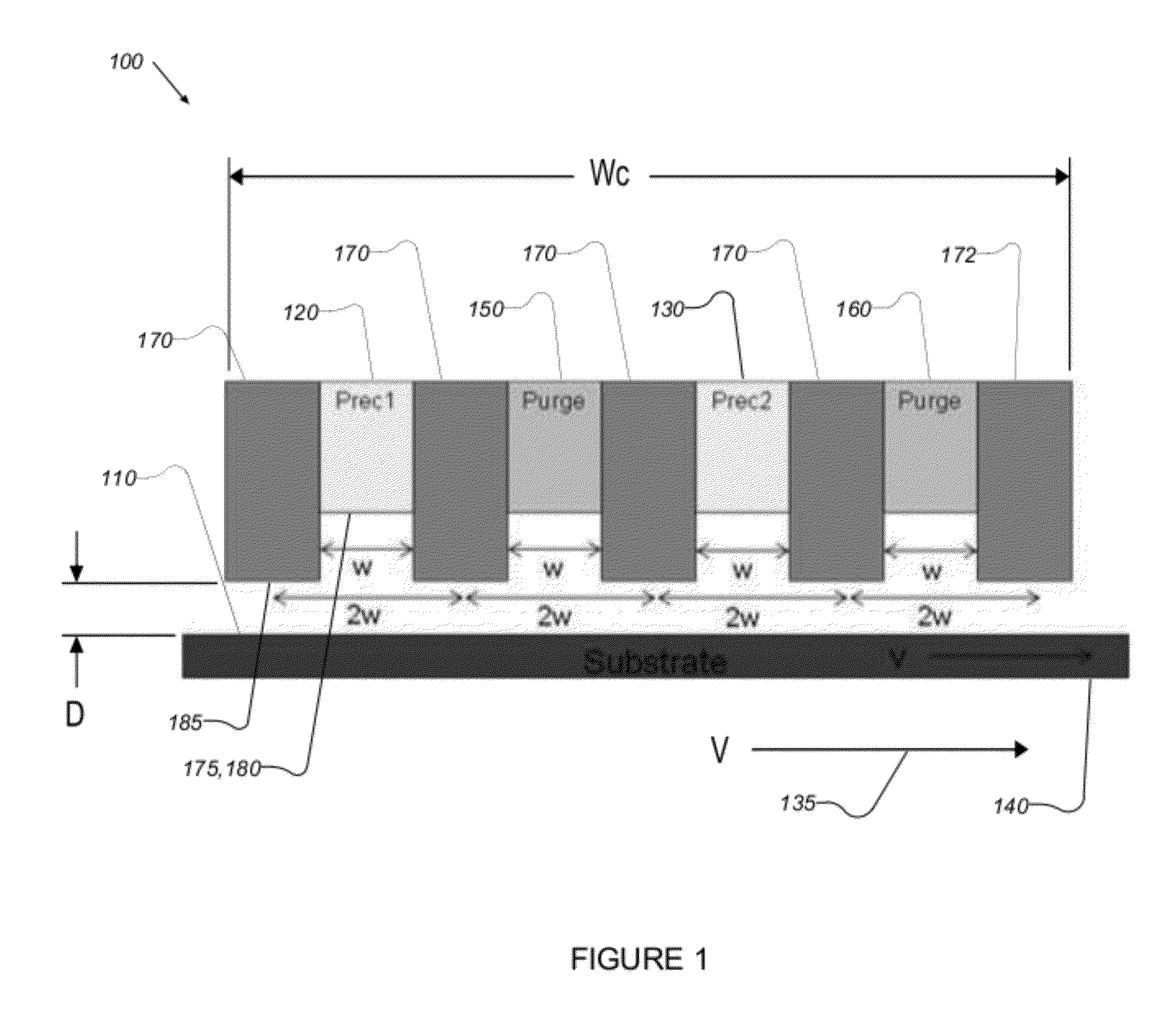
[0061]To understand key aspects of the dwell time more clearly, it is instructive to consider the traditional deposition of an ALD film such as Al2O3. Deposition of Al2O3 begins with the use of a first precursor comprising Trimethylaluminum (TMA) and a second precursor comprising water (H2O). In a traditional ALD vacuum reactor, such as the SAVANNAH ALD system available from Cambridge Nanotech Inc. of Cambridge Mass. based on previous deposition research experience we have estimated that a dwell time of 0.5 ms under atmospheric conditions will replicate the conditions seen for simple saturation of the precursor on the substrate under vacuum conditions. Therefore dwell times of the precursor of 5 msec under atmospheric conditions (which is a factor of 100× greater than required for simple saturation), should provide sufficient saturation even at speeds in excess of 20 m / min.

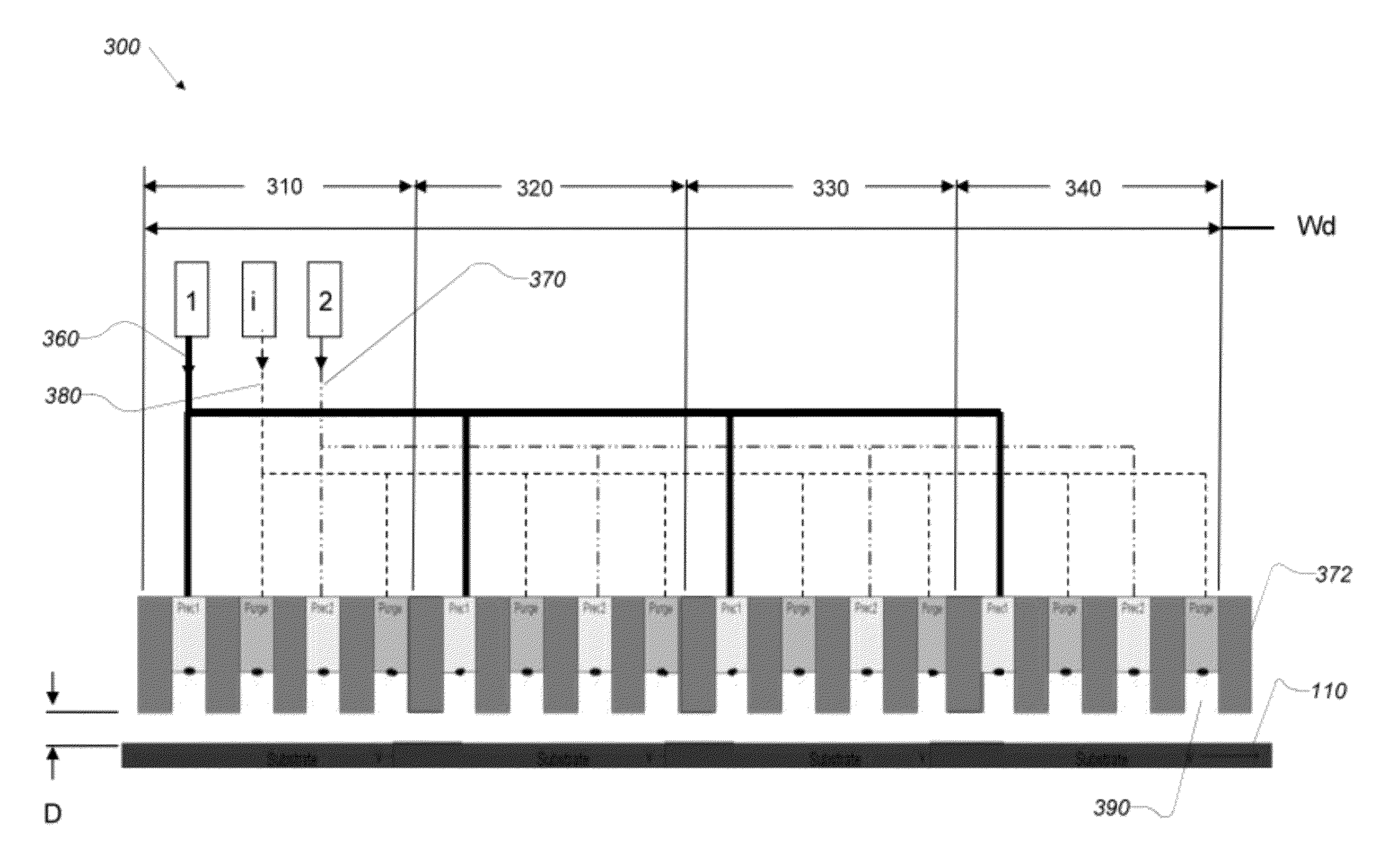
6.2 Channel Width and Substrate Velocity

[0062]Referring now to FIG. 6, the relationship between channel width a...


PUM

PropertyMeasurementUnit
distanceaaaaaaaaaa
distanceaaaaaaaaaa
velocityaaaaaaaaaa

Abstract

An ALD coating system (100) includes a fixed gas manifold (710, 1300) disposed over a moving substrate with a coating surface of the substrate facing precursor orifice plate (930). A gas control system (1400) delivers gas or vapor precursors and inert gas into the fixed gas manifold which directs input gases onto a coating surface of the moving substrate. The gas control system includes a blower (1485) interfaced with the gas manifold which draws gas through the gas manifold to remove unused precursors, inert gas and reaction byproduct from the coating surface. The gas manifold is configured segregate precursor gases at the coating surface to prevent the mixing of dissimilar precursors. The gas manifold may also segregate unused precursor gases in the exhaust system so that the unused precursors can be recovered and reused.

Description

1 CROSS REFERENCE TO RELATED U.S. PATENT APPLICATIONS[0001]This application claims priority under 35 U.S.C. 119(e) based upon Provisional Application Ser. No. 61 / 455,223, entitled Application of ALD Coatings to a Moving Substrate at Atmospheric Pressure, filed Oct. 16, 2010, and further based upon Provisional Application Ser. No. 61 / 455,772, entitled Apparatus for Applying ALD Coatings to a Moving Substrate, filed Oct. 26, 2010, and further based upon Provisional Application Ser. No. 61 / 466,885, entitled ALD Coating System, filed Mar. 23, 2011, all of which are incorporated herein by reference in their entirety2 COPYRIGHT NOTICE[0002]A portion of the disclosure of this patent document may contain material that is subject to copyright protection. The copyright owner has no objection to the facsimile reproduction by anyone of the patent document or the patent disclosure, as it appears in the Patent and Trademark Office patent files or records, but otherwise reserves all copyright righ...

Claims


Application Information

Patent Timeline
Patent Type & Authority Applications(United States)
IPC IPC(8): C23C16/455C23C16/458
CPCC23C16/545C23C16/45551C23C16/448C23C16/54C23C16/4412C23C16/453C23C16/45544C23C16/45557C23C16/45574C23C16/4584
Inventor SERSHEN, MICHAEL J.SUNDARAM, GANESH M.COUTU, ROGER R.BECKER, JILL SVENJADALBERTH, MARK J.
Owner ULTRATECH INT INC
Why Eureka
Try Eureka