
Mold for gravity casting and gravity casting method using the mold

Inactive Publication Date: 2012-06-14
HYUNDAI MOTOR CO LTD +2
View PDF3 Cites 4 Cited by
  • Summary
  • Abstract
  • Description
  • Claims
  • Application Information

AI Technical Summary

Benefits of technology

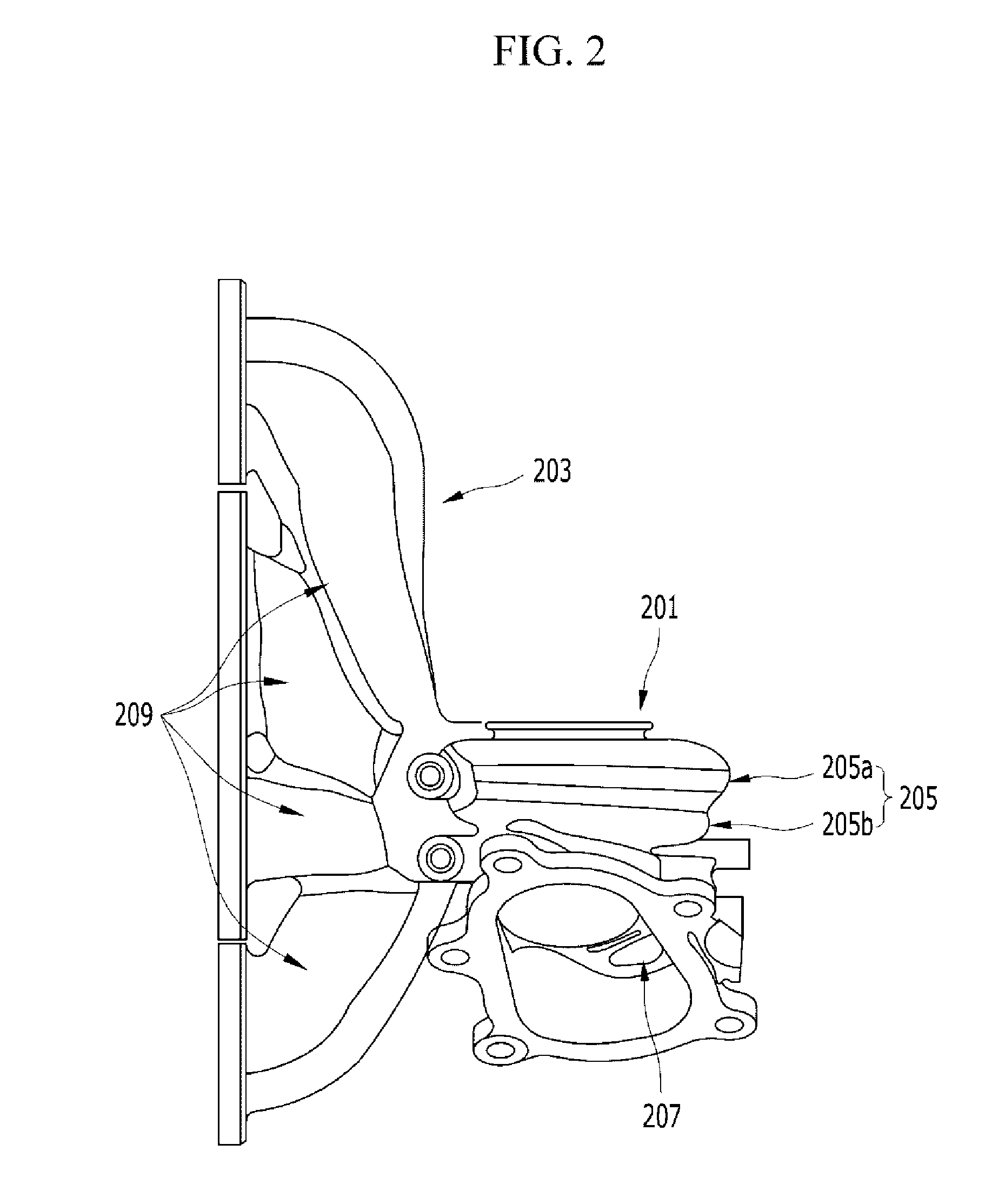
[0028]The present invention has been made in an effort to provide a mold for gravity casting and a gravity casting method using the same having an advantage of the smooth exhaust of an evaporation gas generated from coating, by disposing the end portion of a twin scroll unit (that is, the outlet of a turbine housing) so that the end portion is upward disposed in the direction in which a turbine housing integration type exhaust manifold is cast within a cast and by disposing a rider on the turbine housing side at the center of a position where the twin scroll unit has a minimum cross section.
[0036]As described above, in accordance with the mold for gravity casting and the gravity casting method using the same according to various aspects of the present invention, in the direction in which the turbine housing integration type exhaust manifold is cast within the cast through the separate exhaust runner mold between the first mold and the second mold, the end portion of a twin scroll unit (that is, the outlet of a turbine housing) is disposed so that the end portion is upward disposed, and the rider on the turbine housing side is disposed at the center of a position where the twin scroll unit has a minimum cross section. Accordingly, an evaporation gas generated from coating can be smoothly exhausted.
[0037]Furthermore, although a separate gas exhaust hole connected to the cavity of the twin scroll unit of the turbine housing is not formed, an evaporation gas generated from coasting owing to molten metal is not mixed with the molten metal. Accordingly, a surface adherence phenomenon can be prevented, and residual stress is not generated near the end portion of the twin scroll unit having a narrow cross section. Consequently, product defects, such as contraction holes, can be prevented.

Problems solved by technology

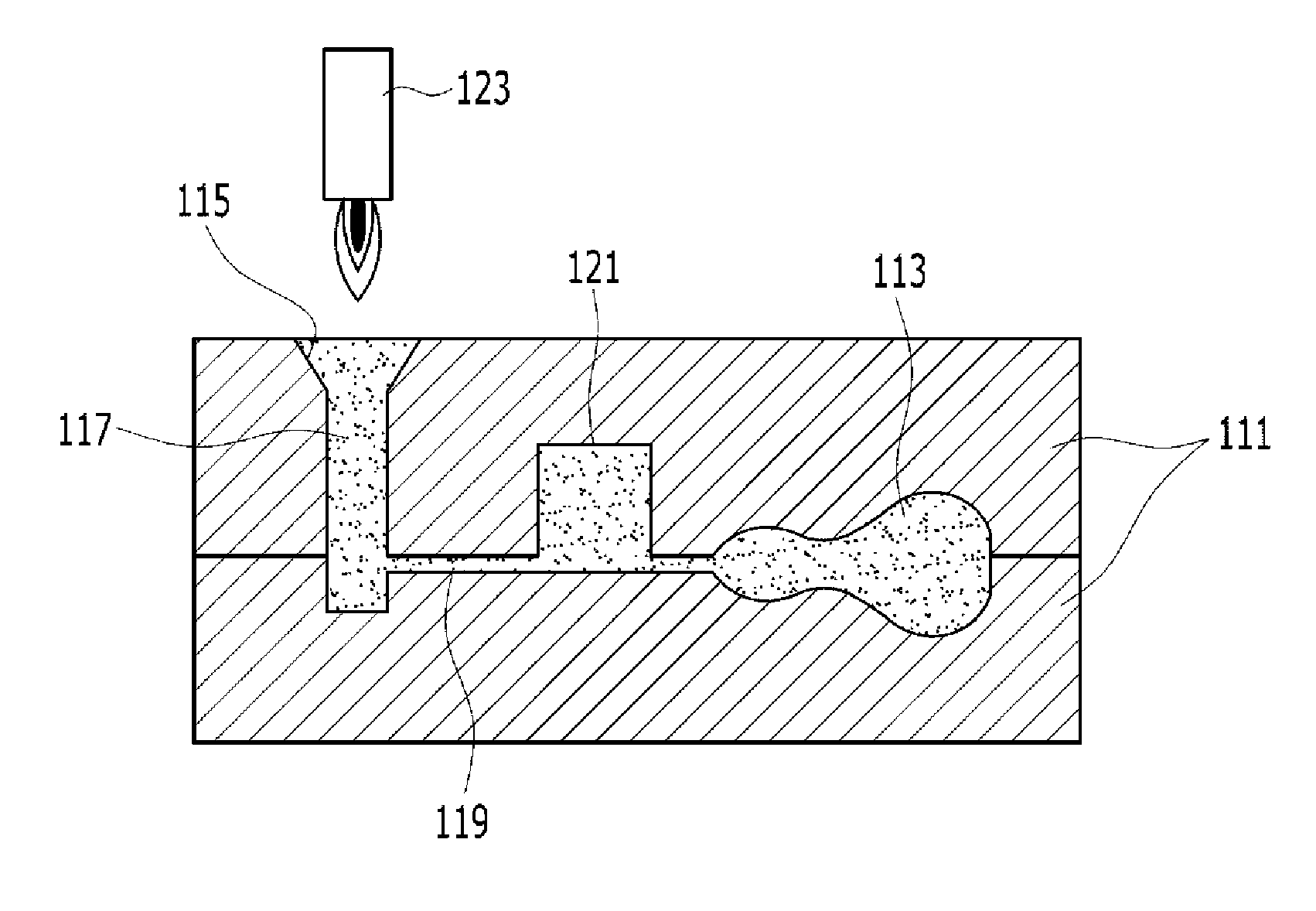
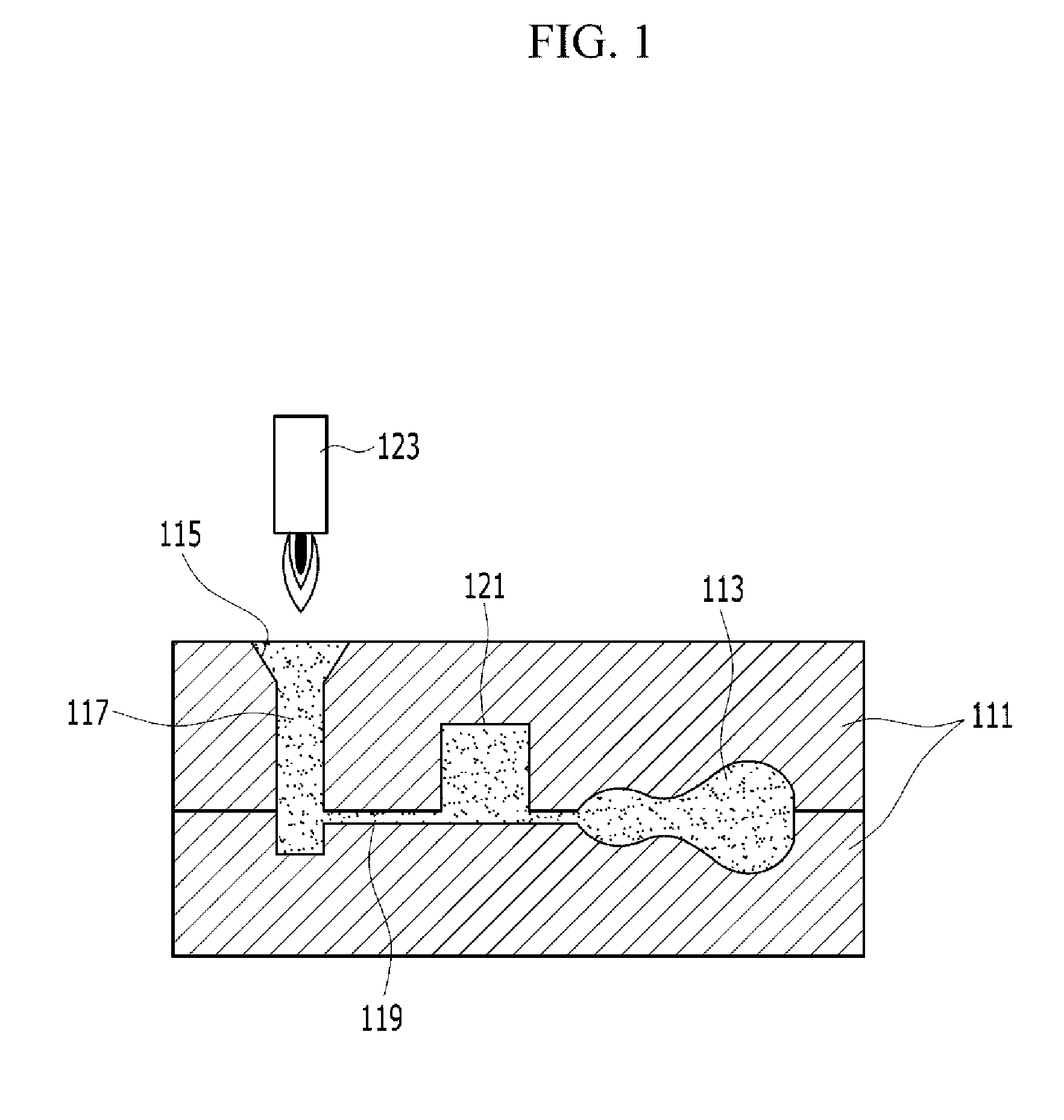
However, there are disadvantages in that the exhaust is not free because the cavity C2 of the turbine housing 201 is narrow and thus defects or a contraction hole are generated in the surface of a product because the molten metal and the gas are mixed.

Method used


Image

  • Mold for gravity casting and gravity casting method using the mold
  • Mold for gravity casting and gravity casting method using the mold
  • Mold for gravity casting and gravity casting method using the mold

Examples


Embodiment Construction

[0049]Reference will now be made in detail to various embodiments of the present invention(s), examples of which are illustrated in the accompanying drawings and described below. While the invention(s) will be described in conjunction with exemplary embodiments, it will be understood that present description is not intended to limit the invention(s) to those exemplary embodiments. On the contrary, the invention(s) is / are intended to cover not only the exemplary embodiments, but also various alternatives, modifications, equivalents and other embodiments, which may be included within the spirit and scope of the invention as defined by the appended claims.

[0050]The mold for gravity casting according to various embodiments, as shown in FIG. 5, has an exhaust manifold 3 integrally formed with a turbine housing 1 for a twin scroll turbocharger. Accordingly, one will appreciate that the exhaust manifold and the turbine housing may be monolithically formed. The turbine housing 1 has a twin ...


PUM

PropertyMeasurementUnit
Diameteraaaaaaaaaa

Abstract

A mold and method for gravity casting may integrally cast a turbine housing having a twin scroll unit and a bypass unit and an exhaust manifold having a plurality of exhaust runner units. A turbine housing-side riser may be formed based on the end portion of the twin scroll unit within a first mold and a second mold in the state where the cavity of the turbine housing is formed so that the end portion of the twin scroll unit which is the outlet of the turbine housing is upward disposed.

Description

CROSS-REFERENCE TO RELATED APPLICATION[0001]This application claims priority to and the benefit of Korean Patent Application No. 10-2010-0125696 filed Dec. 9, 2010, the entire contents of which application is incorporated herein for all purposes by this reference.BACKGROUND OF INVENTION[0002]1. Field of Invention[0003]The present invention relates to a mold for gravity casting and a gravity casting method using the same. More particularly, the present invention relates to a mold for gravity casting and a gravity casting method using the same, in which a turbine housing having a twin scroll unit and an exhaust manifold are integrally cast.[0004]2. Description of Related Art[0005]In general, a gravity casting method is a casting method of solidifying injected molten metal within a cast (that is, a mold) using gravity of the molten metal and is characterized in that the cooling speed of the molten metal is fast and a crystal grain is fine.[0006]FIG. 1 is a schematic view of a common gr...

Claims


Application Information

Patent Timeline
IPC IPC(8): B22D25/02B22C9/10B22C9/24B22C9/00
CPCB22C9/10B22C9/24B22C9/103B22D25/02B22C23/00
Inventor CHU, DONG HOCHOI, DONG-CHANGLEE, JAE-YONG
Owner HYUNDAI MOTOR CO LTD
Learn More